Table of Contents
Advertisement
Quick Links
WEATHER STATION WITH ATOMIC
WEATHER STATION WITH ATOMIC
WEATHER STATION WITH ATOMIC
TIME (3 REMOTE SENSORS
WEATHER STATION WITH ATOMIC
TIME (3 REMOTE SENSORS
WEATHER STATION WITH ATOMIC
TIME (3 REMOTE SENSORS
TIME (3 REMOTE SENSORS INCLUDED)
TIME (3 REMOTE SENSORS
WEATHER STATION WITH ATOMIC
Model: BA030016
Model: BA030016
TIME (3 REMOTE SENSORS
Model: BA030016
USER MANUAL
Model: BA030016
Model: BA030016
Please read this instruction manual carefully and keep it for future reference. This information will
Please read this instruction manual carefully and keep it for future reference. This information will
help you to familiarize yourself with your new Weather Station with Atomic Time (3 Remote
Please read this instruction manual carefully and keep it for future reference. This information will
Please read this instruction manual carefully and keep it for future reference. This information will
help you to familiarize yourself with your new Weather Station with Atomic Time (3 Remote
Sensors Included). This product should only be used as described within these instructions.
help you to familiarize yourself with your new Weather Station with Atomic Time (3 Remote
Please read this instruction manual carefully and keep it for future reference. This information will
Sensors Included). This product should only be used as described within these instructions.
help you to familiarize yourself with your new Weather Station with Atomic Time (3 Remote Sensors
Unauthorized repairs, modifications or changes to the product are prohibited. This product is
Sensors Included). This product should only be used as described within these instructions.
help you to familiarize yourself with your new Weather Station with Atomic Time (3 Remote
Please read this instruction manual carefully and keep it for future reference. This information will
Unauthorized repairs, modifications or changes to the product are prohibited. This product is
Included). This product should only be used as described within these instructions. Unauthorized
intended for home use only.
Unauthorized repairs, modifications or changes to the product are prohibited. This product is
Sensors Included). This product should only be used as described within these instructions.
help you to familiarize yourself with your new Weather Station with Atomic Time (3 Remote
intended for home use only.
repairs, modifications or changes to the product are prohibited. This product is intended for
intended for home use only.
Unauthorized repairs, modifications or changes to the product are prohibited. This product is
Sensors Included). This product should only be used as described within these instructions.
OVERVIEW
intended for home use only.
home use only.
Unauthorized repairs, modifications or changes to the product are prohibited. This product is
OVERVIEW
OVERVIEW
1. [ SNOOZE ] button
intended for home use only.
1. [ SNOOZE ] button
OVERVIEW
2. [ CH/+ ] button
1. [ SNOOZE ] button
2. [ CH/+ ] button
OVERVIEW
3. [ ALARM SET ] button
2. [ CH/+ ] button
1. [ SNOOZE ] button
OVERVIEW
3. [ ALARM SET ] button
1. [ SNOOZE ] button
4. < °C/°F > slide switch
2. [ CH/+ ] button
3. [ ALARM SET ] button
1. [ SNOOZE ] button
4. < °C/°F > slide switch
5. <
2. [ CH/+ ] button
/
>Visual angle slide switch
3. [ ALARM SET ] button
4. < °C/°F > slide switch
2. [ CH/+ ] button
5. <
/
>Visual angle slide switch
6. [ SENSOR ] button
4. < °C/°F > slide switch
5. <
/
>Visual angle slide switch
3. [ ALARM SET ] button
3. [ ALARM SET ] button
6. [ SENSOR ] button
7. [ RCC ] button
6. [ SENSOR ] button
5. <
/
>Visual angle slide switch
4. < °C/°F > slide switch
4. < °C/°F > slide switch
7. [ RCC ] button
8. [ RESET ] button
7. [ RCC ] button
6. [ SENSOR ] button
5. <
/
>Visual angle slide switch
5. < /
>Visual angle slide switch
8. [ RESET ] button
9. [ TIME SET ] button
7. [ RCC ] button
8. [ RESET ] button
6. [ SENSOR ] button
9. [ TIME SET ] button
6. [ SENSOR ] button
10. [ MEM/- ] button
9. [ TIME SET ] button
8. [ RESET ] button
7. [ RCC ] button
10. [ MEM/- ] button
7. [ RCC ] button
11. Wall-mounting hole
9. [ TIME SET ] button
10. [ MEM/- ] button
8. [ RESET ] button
11. Wall-mounting hole
12. Table stand
8. [ RESET ] button
11. Wall-mounting hole
10. [ MEM/- ] button
9. [ TIME SET ] button
12. Table stand
13. Battery compartment
12. Table stand
11. Wall-mounting hole
9. [ TIME SET ] button
10. [ MEM/- ] button
13. Battery compartment
13. Battery compartment
12. Table stand
10. [ MEM/- ] button
11. Wall-mounting hole
13. Battery compartment
12. Table stand
11. Wall-mounting hole
13. Battery compartment
12. Table stand
13. Battery compartment
DISPLAY
DISPLAY
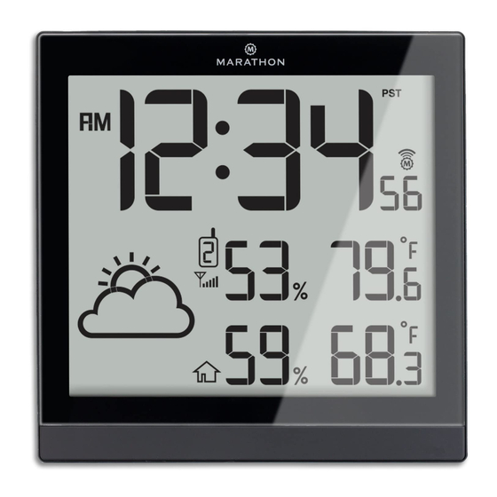
Normal time mode
DISPLAY
DISPLAY
Normal time mode
1. AM/PM (12 Hour format)
DISPLAY
Normal time mode
Normal time mode
1. AM/PM (12 Hour format)
2. Time
1. AM/PM (12 Hour format)
Normal time mode
1. AM/PM (12 Hour format)
DISPLAY
2. Time
2. Time
1. AM/PM (12 Hour format)
Normal time mode
2. Time
3. Outdoor humidity
4. Sensor signal indicator
3. Outdoor humidity
2. Time
1. AM/PM (12 Hour format)
4. Sensor signal indicator
3. Outdoor humidity
5. Weather forecast indicator
3. Outdoor humidity
4. Sensor signal indicator
2. Time
5. Weather forecast indicator
4. Sensor signal indicator
6. Low battery indicator for sensor
5. Weather forecast indicator
4. Sensor signal indicator
3. Outdoor humidity
6. Low battery indicator for sensor
5. Weather forecast indicator
5. Weather forecast indicator
6. Low battery indicator for sensor
4. Sensor signal indicator
7. Indoor humidity
7. Indoor humidity
6. Low battery indicator for sensor
6. Low battery indicator for sensor
5. Weather forecast indicator
8. Indoor temperature
9. MAX/MIN indicator
8. Indoor temperature
7. Indoor humidity
7. Indoor humidity
6. Low battery indicator for sensor
9. MAX/MIN indicator
9. MAX/MIN indicator
8. Indoor temperature
7. Indoor humidity
8. Indoor temperature
10. Outdoor temperature
9. MAX/MIN indicator
10. Outdoor temperature
8. Indoor temperature
11. Ice Alert on
9. MAX/MIN indicator
12. RC signal strength indicator
10. Outdoor temperature
11. Ice Alert on
9. MAX/MIN indicator
12. RC signal strength indicator
10. Outdoor temperature
13. DST
12. RC signal strength indicator
11. Ice Alert on
10. Outdoor temperature
13. DST
14. Time zone indicator
11. Ice Alert on
13. DST
12. RC signal strength indicator
11. Ice Alert on
14. Time zone indicator
14. Time zone indicator
13. DST
12. RC signal strength indicator
12. RC signal strength indicator
14. Time zone indicator
13. DST
13. DST
Alarm time mode
14. Time zone indicator
14. Time zone indicator
Alarm time mode
1. Alarm time
Alarm time mode
1. Alarm time
2. Alarm icon/Alarm on
1. Alarm time
Alarm time mode
2. Alarm icon/Alarm on
3. Alarm mode indicator
2. Alarm icon/Alarm on
1. Alarm time
Alarm time mode
3. Alarm mode indicator
3. Alarm mode indicator
2. Alarm icon/Alarm on
Alarm time mode
1. Alarm time
3. Alarm mode indicator
2. Alarm icon/Alarm on
1. Alarm time
3. Alarm mode indicator
2. Alarm icon/Alarm on
3. Alarm mode indicator
C8458A-PD16055M Marathon 2016.5.18 indd.indd
1
INCLUDED)
INCLUDED)
INCLUDED)
Model: BA030016
INCLUDED)
USER MANUAL
USER MANUAL
USER MANUAL
INCLUDED)
USER MANUAL
USER MANUAL
1
1
2
1
2
2
1
3
3
2
3
1
2
3
3
4
5
4
5
4
5
4
5
11
11
4
5
11
11
11
12
12
12
13
12
13
13
12
13
13
1
1
1
2
2
1
2
3
3
2
1
4
3
4
2
4
3
5
5
4
5
3
6
5
4
6
6
7
5
7
6
7
7
6
7
1
1
1
1
1
TRANSMITTER
TRANSMITTER
TRANSMITTER
TRANSMITTER
TRANSMITTER
TRANSMITTER
1
1. LED indicator:
1. LED indicator:
- Flashes when the remote unit transmits a reading.
1. LED indicator:
- Flashes when the remote unit transmits a reading.
1. LED indicator:
2. Wall mounting hole
- Flashes when the remote unit transmits a reading.
2. Wall mounting hole
- Flashes when the remote unit transmits a reading.
1. LED indicator:
- Use to affix the transmitter on the wall.
2. Wall mounting hole
- Use to affix the transmitter on the wall.
2. Wall mounting hole
- Flashes when the remote unit transmits a reading.
3. [ RESET ] button
1. LED indicator:
- Use to affix the transmitter on the wall.
3.
[ RESET ]
button
- Use to affix the transmitter on the wall.
2. Wall mounting hole
- Flashes when the remote unit transmits a reading.
- Press to reset the transmitter.
[ RESET ]
3.
button
- Press to reset the transmitter.
3.
[ RESET ]
button
- Use to affix the transmitter on the wall.
2. Wall mounting hole
4. [ CHANNEL ] slide switch
- Press to reset the transmitter.
4.
[ CHANNEL ]
- Press to reset the transmitter.
3.
[ RESET ]
button
- Use to affix the transmitter on the wall.
4.
[ CHANNEL ]
- Assign the transmitter to Channel 1, 2 or 3.
slide switch
- Assign the transmitter to Channel 1, 2 or 3.
4.
[ CHANNEL ]
- Press to reset the transmitter.
3.
[ RESET ]
button
5. Battery compartment
- Assign the transmitter to Channel 1, 2 or 3.
5. Battery compartment
4.
- Assign the transmitter to Channel 1, 2 or 3.
[ CHANNEL ]
- Press to reset the transmitter.
5. Battery compartment
- Accommodates 2 x AA size batteries.
- Accommodates 2 x AA size batteries.
5. Battery compartment
- Assign the transmitter to Channel 1, 2 or 3.
4.
[ CHANNEL ]
- Accommodates 2 x AA size batteries.
GETTING STARTED
- Accommodates 2 x AA size batteries.
5. Battery compartment
- Assign the transmitter to Channel 1, 2 or 3.
GETTING STARTED
• Remove the battery door of the clock and sensors.
- Accommodates 2 x AA size batteries.
5. Battery compartment
GETTING STARTED
● Remove the battery door of the clock and sensors.
• Insert 4 new AA size batteries to the clock, and 2 to the sensors according to the "+/-" polarity mark
GETTING STARTED
- Accommodates 2 x AA size batteries.
● Remove the battery door of the clock and sensors.
● Insert 4 new AA size batteries to the clock, and 2 to the sensors according to
on the battery compartment.
● Remove the battery door of the clock and sensors.
GETTING STARTED
● Insert 4 new AA size batteries to the clock, and 2 to the sensors according to
the "+/-" polarity mark on the battery compartment.
● Insert 4 new AA size batteries to the clock, and 2 to the sensors according to
• Replace the battery doors.
● Remove the battery door of the clock and sensors.
GETTING STARTED
the "+/-" polarity mark on the battery compartment.
● Replace the battery doors.
• Once the batteries are inserted, full segment of the LCD will be shown briefly.
the "+/-" polarity mark on the battery compartment.
● Insert 4 new AA size batteries to the clock, and 2 to the sensors according to
● Remove the battery door of the clock and sensors.
● Replace the battery doors.
● Once the batteries are inserted, full segment of the LCD will be shown briefly.
● Replace the battery doors.
the "+/-" polarity mark on the battery compartment.
• Press the [ RESET ] button of main unit fi rst, then press the [ RESET ] button on each transmitter.
● Insert 4 new AA size batteries to the clock, and 2 to the sensors according to
● Once the batteries are inserted, full segment of the LCD will be shown briefly.
● Press the [ RESET ] button of main unit rst, then press the [ RESET ] button on each transmitter.
● Replace the battery doors.
● Once the batteries are inserted, full segment of the LCD will be shown briefly.
• The main unit will automatically receive 433 MHz signal from the transmitters for the channel test
the "+/-" polarity mark on the battery compartment.
● Press the [ RESET ] button of main unit rst, then press the [ RESET ] button on each transmitter.
● The main unit will automatically receive 433 MHz signal from the transmitters for the channel test
● Press the [ RESET ] button of main unit rst, then press the [ RESET ] button on each transmitter.
● Once the batteries are inserted, full segment of the LCD will be shown briefly.
within 8 seconds.
● Replace the battery doors.
● The main unit will automatically receive 433 MHz signal from the transmitters for the channel test
within 8 seconds.
● The main unit will automatically receive 433 MHz signal from the transmitters for the channel test
● Press the [ RESET ] button of main unit rst, then press the [ RESET ] button on each transmitter.
• The channel test will last for 5 minutes, at which time the RC signal reception sequence will
● Once the batteries are inserted, full segment of the LCD will be shown briefly.
within 8 seconds.
● The channel test will last for 5 minutes, at which time the RC signal reception sequence will
within 8 seconds.
● The main unit will automatically receive 433 MHz signal from the transmitters for the channel test
commence automatically.
● Press the [ RESET ] button of main unit rst, then press the [ RESET ] button on each transmitter.
● The channel test will last for 5 minutes, at which time the RC signal reception sequence will
commence automatically.
● The channel test will last for 5 minutes, at which time the RC signal reception sequence will
within 8 seconds.
10
NOTE:
● The main unit will automatically receive 433 MHz signal from the transmitters for the channel test
commence automatically.
commence automatically.
10
● The channel test will last for 5 minutes, at which time the RC signal reception sequence will
NOTE:
within 8 seconds.
10
If no display appears on the LCD after inserting the batteries, press the [ RESET ] button by
9
commence automatically.
NOTE:
9
● The channel test will last for 5 minutes, at which time the RC signal reception sequence will
If no display appears on the LCD after inserting the batteries, press the [ RESET ] button by
10
NOTE:
using a pointed instrument. In some cases, you may not receive the RC signal immediately,
9
If no display appears on the LCD after inserting the batteries, press the [ RESET ] button by
using a pointed instrument. In some cases, you may not receive the RC signal immediately, due
commence automatically.
NOTE:
If no display appears on the LCD after inserting the batteries, press the [ RESET ] button by
due to atmospheric disturbance. The best reception often occurs during nighttime.
10
9
using a pointed instrument. In some cases, you may not receive the RC signal immediately, due
to atmospheric disturbance. The best reception often occurs during nighttime.
using a pointed instrument. In some cases, you may not receive the RC signal immediately, due
If no display appears on the LCD after inserting the batteries, press the [ RESET ] button by
HOW TO PAIR MAIN UNIT AND SENSOR
NOTE:
to atmospheric disturbance. The best reception often occurs during nighttime.
9
6
7
8
to atmospheric disturbance. The best reception often occurs during nighttime.
using a pointed instrument. In some cases, you may not receive the RC signal immediately, due
1. Press [ CH / + ] button on main unit to select a channel.
If no display appears on the LCD after inserting the batteries, press the [ RESET ] button by
6
7
8
HOW TO PAIR MAIN UNIT AND SENSOR
to atmospheric disturbance. The best reception often occurs during nighttime.
6
7
8
2. On sensor, slide channel switch to corresponding channel. (For additional sensors, select a
using a pointed instrument. In some cases, you may not receive the RC signal immediately, due
HOW TO PAIR MAIN UNIT AND SENSOR
HOW TO PAIR MAIN UNIT AND SENSOR
1. Press [ CH / + ] button on main unit to select a channel.
6
7
8
different channel). Press [ RESET ] button.
to atmospheric disturbance. The best reception often occurs during nighttime.
1. Press [ CH / + ] button on main unit to select a channel.
HOW TO PAIR MAIN UNIT AND SENSOR
2. On sensor, slide channel switch to corresponding channel. (For additional sensors, select a
1. Press [ CH / + ] button on main unit to select a channel.
3. Press [ SENSOR ] on main unit to initiate the search for sensor.
6
7
8
2. On sensor, slide channel switch to corresponding channel. (For additional sensors, select a
different channel). Press [ RESET ] button.
2. On sensor, slide channel switch to corresponding channel. (For additional sensors, select a
1. Press [ CH / + ] button on main unit to select a channel.
4. Repeat sequence for additional sensors.
HOW TO PAIR MAIN UNIT AND SENSOR
different channel). Press [ RESET ] button.
3. Press [ SENSOR ] on main unit to initiate the search for sensor.
2. On sensor, slide channel switch to corresponding channel. (For additional sensors, select a
different channel). Press [ RESET ] button.
DAYLIGHT SAVING TIME (DST)
1. Press [ CH / + ] button on main unit to select a channel.
3. Press [ SENSOR ] on main unit to initiate the search for sensor.
4. Repeat sequence for additional sensors.
3. Press [ SENSOR ] on main unit to initiate the search for sensor.
different channel). Press [ RESET ] button.
The clock will automatically advance the time by one hour in the spring and back an hour in the
2. On sensor, slide channel switch to corresponding channel. (For additional sensors, select a
4. Repeat sequence for additional sensors.
4. Repeat sequence for additional sensors.
3. Press [ SENSOR ] on main unit to initiate the search for sensor.
fall, provided that the DST function is enabled.
different channel). Press [ RESET ] button.
DAYLIGHT SAVING TIME (DST)
DAYLIGHT SAVING TIME (DST)
4. Repeat sequence for additional sensors.
3. Press [ SENSOR ] on main unit to initiate the search for sensor.
DST function is set to AUTO by default.
The clock will automatically advance the time by one hour in the spring and back an hour in the
DAYLIGHT SAVING TIME (DST)
The clock will automatically advance the time by one hour in the spring and back an hour in the
4. Repeat sequence for additional sensors.
WIRELESS SENSOR RECEPTION
fall, provided that the DST function is enabled.
The clock will automatically advance the time by one hour in the spring and back an hour in the
DAYLIGHT SAVING TIME (DST)
fall, provided that the DST function is enabled.
DST function is set to AUTO by default.
If the main unit receives wireless sensor signal successfully, the signal icon "
fall, provided that the DST function is enabled.
The clock will automatically advance the time by one hour in the spring and back an hour in the
DAYLIGHT SAVING TIME (DST)
DST function is set to AUTO by default.
If it cannot receive sensor signal or signal is lost, "
DST function is set to AUTO by default.
fall, provided that the DST function is enabled.
The clock will automatically advance the time by one hour in the spring and back an hour in the
WIRELESS SENSOR RECEPTION
RECEPTION OF RADIO CONTROLLED SIGNAL
DST function is set to AUTO by default.
fall, provided that the DST function is enabled.
WIRELESS SENSOR RECEPTION
If the main unit receives wireless sensor signal successfully, the signal icon "
WIRELESS SENSOR RECEPTION
The time and date are radio-controlled. The current time and date are automatically
DST function is set to AUTO by default.
If the main unit receives wireless sensor signal successfully, the signal icon "
If it cannot receive sensor signal or signal is lost, "
If the main unit receives wireless sensor signal successfully, the signal icon "
WIRELESS SENSOR RECEPTION
synchronized with the time signal transmitted from WWVB station in Colorado.
If it cannot receive sensor signal or signal is lost, "
If the main unit receives wireless sensor signal successfully, the signal icon "
If it cannot receive sensor signal or signal is lost, "
14
• The clock automatically carries out 4 periodic synchronization procedures (2:00 AM, 8:00 AM,
WIRELESS SENSOR RECEPTION
14
RECEPTION OF RADIO CONTROLLED SIGNAL
13
If it cannot receive sensor signal or signal is lost, "
14
2:00 PM and 8:00 PM daily) with the RC signal to correct any deviations from the exact time.
If the main unit receives wireless sensor signal successfully, the signal icon "
RECEPTION OF RADIO CONTROLLED SIGNAL
13
The time and date are radio-controlled. The current time and date are automatically
RECEPTION OF RADIO CONTROLLED SIGNAL
12
13
• Once the unit synchronizes successfully to the RC signal, the signal icon "
14
If it cannot receive sensor signal or signal is lost, "
The time and date are radio-controlled. The current time and date are automatically
12
synchronized with the time signal transmitted from WWVB station in Colorado.
RECEPTION OF RADIO CONTROLLED SIGNAL
The time and date are radio-controlled. The current time and date are automatically
12
13
displayed. Each synchronization process will take between 6 to 16 minutes.
14
synchronized with the time signal transmitted from WWVB station in Colorado.
● The clock automatically carries out 4 periodic synchronization procedures (2:00 AM, 8:00 AM,
11
synchronized with the time signal transmitted from WWVB station in Colorado.
The time and date are radio-controlled. The current time and date are automatically
12
• To manually start or stop the RC signal reception procedure, press the [ RCC ] button.
RECEPTION OF RADIO CONTROLLED SIGNAL
13
● The clock automatically carries out 4 periodic synchronization procedures (2:00 AM, 8:00 AM,
11
2:00 PM and 8:00 PM daily) with the RC signal to correct any deviations from the exact time.
● The clock automatically carries out 4 periodic synchronization procedures (2:00 AM, 8:00 AM,
synchronized with the time signal transmitted from WWVB station in Colorado.
11
10
NOTE:
The time and date are radio-controlled. The current time and date are automatically
12
2:00 PM and 8:00 PM daily) with the RC signal to correct any deviations from the exact time.
10
● The clock automatically carries out 4 periodic synchronization procedures (2:00 AM, 8:00 AM,
● Once the unit synchronizes successfully to the RC signal, the signal icon "
2:00 PM and 8:00 PM daily) with the RC signal to correct any deviations from the exact time.
11
10
synchronized with the time signal transmitted from WWVB station in Colorado.
• The strength of radio-controlled time signal from the transmitter tower may be affected by
9
● Once the unit synchronizes successfully to the RC signal, the signal icon "
displayed. Each synchronization process will take between 6 to 16 minutes.
2:00 PM and 8:00 PM daily) with the RC signal to correct any deviations from the exact time.
● Once the unit synchronizes successfully to the RC signal, the signal icon "
9
● The clock automatically carries out 4 periodic synchronization procedures (2:00 AM, 8:00 AM,
geographical location or surrounding buildings.
11
10
9
displayed. Each synchronization process will take between 6 to 16 minutes.
8
● To manually start or stop the RC signal reception procedure, press the [ RCC ] button.
displayed. Each synchronization process will take between 6 to 16 minutes.
● Once the unit synchronizes successfully to the RC signal, the signal icon "
2:00 PM and 8:00 PM daily) with the RC signal to correct any deviations from the exact time.
8
• Always place the unit away from interfering sources such as TV set, computer, etc.
● To manually start or stop the RC signal reception procedure, press the [ RCC ] button.
9
10
8
● To manually start or stop the RC signal reception procedure, press the [ RCC ] button.
displayed. Each synchronization process will take between 6 to 16 minutes.
● Once the unit synchronizes successfully to the RC signal, the signal icon "
• Avoid placing the unit on or next to metal surfaces.
8
NOTE:
9
● To manually start or stop the RC signal reception procedure, press the [ RCC ] button.
displayed. Each synchronization process will take between 6 to 16 minutes.
• Closed areas such as airports, basements, tower blocks, or factories may not receive a
NOTE:
●
The strength of radio-controlled time signal from the transmitter tower may be affected by
NOTE:
8
● To manually start or stop the RC signal reception procedure, press the [ RCC ] button.
strong signal.
●
The strength of radio-controlled time signal from the transmitter tower may be affected by
geographical location or surrounding buildings.
●
NOTE:
The strength of radio-controlled time signal from the transmitter tower may be affected by
SIGNAL RECEPTION INDICATOR
geographical location or surrounding buildings.
●
Always place the unit away from interfering sources such as TV set, computer, etc.
geographical location or surrounding buildings.
●
The strength of radio-controlled time signal from the transmitter tower may be affected by
NOTE:
●
Always place the unit away from interfering sources such as TV set, computer, etc.
The signal indicator displays signal strength in 4 levels. Wave segment fl ashing means time signals
●
Avoid placing the unit on or next to metal surfaces.
●
Always place the unit away from interfering sources such as TV set, computer, etc.
geographical location or surrounding buildings.
●
The strength of radio-controlled time signal from the transmitter tower may be affected by
●
Avoid placing the unit on or next to metal surfaces.
are being received. The signal quality could be classified into 4 types:
●
Closed areas such as airports, basements, tower blocks, or factories may not receive a
●
●
Always place the unit away from interfering sources such as TV set, computer, etc.
Avoid placing the unit on or next to metal surfaces.
geographical location or surrounding buildings.
●
Closed areas such as airports, basements, tower blocks, or factories may not receive a
strong signal.
●
●
Closed areas such as airports, basements, tower blocks, or factories may not receive a
Avoid placing the unit on or next to metal surfaces.
●
Always place the unit away from interfering sources such as TV set, computer, etc.
strong signal.
SIGNAL RECEPTION INDICATOR
strong signal.
●
Closed areas such as airports, basements, tower blocks, or factories may not receive a
●
Avoid placing the unit on or next to metal surfaces.
SIGNAL RECEPTION INDICATOR
The signal indicator displays signal strength in 4 levels. Wave segment ashing means time signals
SIGNAL RECEPTION INDICATOR
strong signal.
●
Closed areas such as airports, basements, tower blocks, or factories may not receive a
The signal indicator displays signal strength in 4 levels. Wave segment ashing means time signals
are being received. The signal quality could be classi ed into 4 types:
The signal indicator displays signal strength in 4 levels. Wave segment ashing means time signals
SIGNAL RECEPTION INDICATOR
strong signal.
2
are being received. The signal quality could be classi ed into 4 types:
are being received. The signal quality could be classi ed into 4 types:
The signal indicator displays signal strength in 4 levels. Wave segment ashing means time signals
2
SIGNAL RECEPTION INDICATOR
2
are being received. The signal quality could be classi ed into 4 types:
The signal indicator displays signal strength in 4 levels. Wave segment ashing means time signals
2
3
TIME ZONE SETTING
are being received. The signal quality could be classi ed into 4 types:
3
2
3
Your clock is designed to display time for different time zones. Please refer to the SETTING THE
TIME AND CALENDAR section to set your desired time zone in following order:
3
PST (Pacific)
3
TIME ZONE SETTING
SETTING THE TIME AND CALENDAR
TIME ZONE SETTING
Your clock is designed to display time for different time zones. Please refer to the SETTING THE
TIME ZONE SETTING
• In normal time mode, press and hold [ TIME SET ] button for 3 seconds until the 12/24 Hr
Your clock is designed to display time for different time zones. Please refer to the SETTING THE
TIME AND CALENDAR section to set your desired time zone in following order: PST (Paci c)
TIME ZONE SETTING
Your clock is designed to display time for different time zones. Please refer to the SETTING THE
flashes on the display.
TIME AND CALENDAR section to set your desired time zone in following order: PST (Paci c)
MST (Mountain)
TIME AND CALENDAR section to set your desired time zone in following order: PST (Paci c)
Your clock is designed to display time for different time zones. Please refer to the SETTING THE
TIME ZONE SETTING
MST (Mountain)
• Press [ CH/+ ] or [ MEM/- ] button to choose 12 or 24 Hour format.
MST (Mountain)
TIME AND CALENDAR section to set your desired time zone in following order: PST (Paci c)
Your clock is designed to display time for different time zones. Please refer to the SETTING THE
• Press [ TIME SET ] button again until Hour digit flashes and press [ CH/+ ] or [ MEM/- ] button
SETTING THE TIME AND CALENDAR
MST (Mountain)
TIME AND CALENDAR section to set your desired time zone in following order: PST (Paci c)
SETTING THE TIME AND CALENDAR
to adjust its value.
● In normal time mode, press and hold [ TIME SET ] button for 3 seconds until the 12/24 Hr
SETTING THE TIME AND CALENDAR
MST (Mountain)
● In normal time mode, press and hold [ TIME SET ] button for 3 seconds until the 12/24 Hr
• Repeat the above operations to set the time and calendar in this sequence:
flashes on the display.
SETTING THE TIME AND CALENDAR
● In normal time mode, press and hold [ TIME SET ] button for 3 seconds until the 12/24 Hr
flashes on the display.
12/24Hr
Hour
● Press [ CH/+ ] or [ MEM/- ] button to choose 12 or 24 Hour format.
flashes on the display.
● In normal time mode, press and hold [ TIME SET ] button for 3 seconds until the 12/24 Hr
SETTING THE TIME AND CALENDAR
● Press [ CH/+ ] or [ MEM/- ] button to choose 12 or 24 Hour format.
• Press [ TIME SET ] button to save the setting and exit setup mode, or the clock will automatically
● Press [ TIME SET ] button again until Hour digit flashes and press [ CH/+ ] or [ MEM/- ] button
● Press [ CH/+ ] or [ MEM/- ] button to choose 12 or 24 Hour format.
flashes on the display.
● In normal time mode, press and hold [ TIME SET ] button for 3 seconds until the 12/24 Hr
● Press [ TIME SET ] button again until Hour digit flashes and press [ CH/+ ] or [ MEM/- ] button
exit after 30 seconds if no buttons are pressed.
to adjust it's value.
● Press [ TIME SET ] button again until Hour digit flashes and press [ CH/+ ] or [ MEM/- ] button
● Press [ CH/+ ] or [ MEM/- ] button to choose 12 or 24 Hour format.
flashes on the display.
to adjust it's value.
● Press [ TIME SET ] button again until Hour digit flashes and press [ CH/+ ] or [ MEM/- ] button
to adjust it's value.
● Press [ CH/+ ] or [ MEM/- ] button to choose 12 or 24 Hour format.
to adjust it's value.
● Press [ TIME SET ] button again until Hour digit flashes and press [ CH/+ ] or [ MEM/- ] button
to adjust it's value.
2
1
2
2
1
3
2
1
3
3
2
1
3
5
3
5
5
5
5
slide switch
slide switch
slide switch
slide switch
" icon is displayed.
" icon is displayed.
" icon is displayed.
" icon is displayed.
" icon is displayed.
" icon is displayed.
or
or
No signal
or
No signal
or
No signal
No signal
Acceptable signal
or
MST (Mountain)
CST (Central)
EST (Eastern)
Acceptable signal
Acceptable signal
No signal
Acceptable signal
Acceptable signal
CST (Central)
EST (Eastern)
CST (Central)
EST (Eastern)
CST (Central)
EST (Eastern)
CST (Central)
EST (Eastern)
CST (Central)
EST (Eastern)
Minute
Second
Time Zone
4
4
4
4
4
" is displayed.
" is displayed.
" is displayed.
" is displayed.
" is displayed.
" is displayed.
" will be
" will be
" will be
" will be
" will be
" will be
Weak signal
Weak signal
Weak signal
Weak signal
Excellent signal
Excellent signal
Excellent signal
Weak signal
Excellent signal
Excellent signal
2016/5/18
11:22:01
Advertisement
Table of Contents

Related Manuals for Marathon BA030016


Summary of Contents for Marathon BA030016
- Page 1 ● Press [ CH/+ ] or [ MEM/- ] button to choose 12 or 24 Hour format. to adjust it's value. ● Press [ TIME SET ] button again until Hour digit flashes and press [ CH/+ ] or [ MEM/- ] button to adjust it's value. C8458A-PD16055M Marathon 2016.5.18 indd.indd 2016/5/18 11:22:01...
- Page 2 However, there is no guarantee that interference will not occur in a particular installation. If this Select Temperature Unit Company Name: Marathon Watch Company Ltd. e [ °C / °F ] switch on main unit to <°C> or <°F> position.
Need help?
Do you have a question about the BA030016 and is the answer not in the manual?
Questions and answers
How do you change to EST
To change the time to EST (Eastern Standard Time) on a Marathon BA030016:
1. Press and hold the [TIME SET] button for 3 seconds until the 12/24 Hr option appears.
2. Use the [CH/+] or [MEM/-] button to adjust the setting as needed.
3. Continue pressing [TIME SET] to cycle through settings until the time zone option appears.
4. Select EST (Eastern Standard Time) by using the [CH/+] or [MEM/-] button.
5. Press [TIME SET] again to save the setting and exit. If no buttons are pressed for 30 seconds, the clock will automatically exit setup mode.
This answer is automatically generated