Table of Contents
Advertisement
Quick Links
Advertisement
Table of Contents

Related Manuals for Motostar DOMUSTAR


Summary of Contents for Motostar DOMUSTAR
- Page 1 AUTOMATION FOR GARAGE DOOR DOMUSTAR INSTALLATION MANUAL...
-
Page 2: Table Of Contents
INDEX Description of the parts for installation ......page Description of the parts of the motor ....... page General characteristics ........... page General characteristics of the motor ....... page Characteristics of the transmission guide ....... page External dimensions ............page Examples of applications .......... -
Page 3: Description Of The Parts For Installation
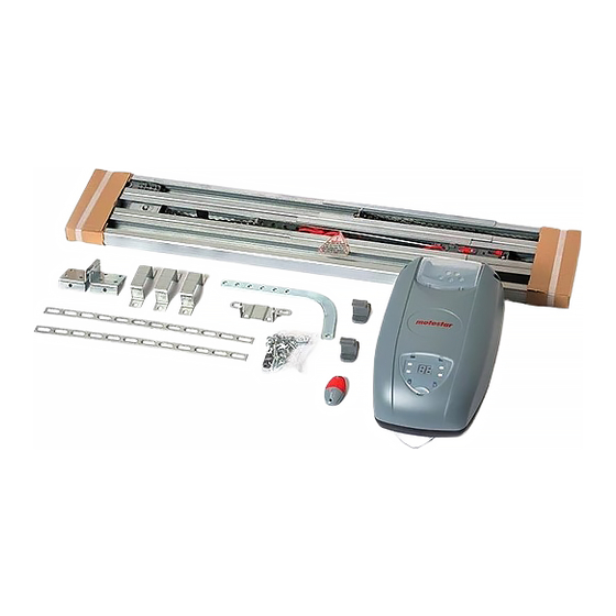
DESCRIPTION OF THE PARTS FOR INSTALLATION Transmission Guide Gear Motor Flashing Light Transmission Arm Antenna Lock Pushbutton Safety rib Photocells Transmitter DESCRIPTION OF THE PARTS OF THE MOTOR Battery back-up holder Battery 12V-6Ah (optional) (optional) Transformer Catch Control panel Plug Motor with Courtesy light encoder... -
Page 4: General Characteristics
GENERAL CHARACTERISTICS Pull automation for counter-weighted garage-type spring and sectional closures, with 230V AC power supply with IP40 protection, equipped with: - self-learning of the code between transmitter and radio receiver; - chain transmission guide (pre-assembled in two pieces) fi xed in the centre of the door for a regular and constant door movement;... -
Page 5: External Dimensions
EXTERNAL DIMENSIONS EXAMPLES OF APPLICATION A - Sectional door B - Spring balanced over- head door C - Overhead door with counterweight balancing or canopy door. MGA100 adaptor arm required. -
Page 6: Unit Assembly
UNIT ASSEMBLY PREPARING THE TRASMISSION GUIDE 180˚ - Turn the guide 180° as indicated in the fi gure; M6x12 - Insert the joint bracket into the guide Guide and fi x it with the Guide Ø6 screws supplied; Joint bracket - Adjust the chain ten- sion using the nut. - Page 7 Ref.1 b) for the counter- weighted garage- type doors and a springs, check the point maximum of sliding of the wing (Ref. 1) and secure the bracket on the fi xed frame, with suitable screws or rivets. Please note: for counter-weighted over-edge garage- type doors, the...
- Page 8 FIXING THE DRAG LEVER - Secure the trans- mission arm centrally to the upper traverse of the door using the rivets supplied; - Assemble the release knob tighten- ing it on the pawl of the pre-assembled release unit and se- cure it in the recom- mended position with the lock nut;...
- Page 9 RELEASING THE GEARMOTOR UNCLAMP - Unscrew the knob by turning it in the direc- tion illustrated (fi g. 5); the re-activation of the Fig. 5 LOCK release will take place automatically at the fi rst manoeuvre, by returning the knob to the initial position.
- Page 10 CONTROL BOARD DESCRIPTION The board is powered by a power supply Connected accessories socket (230V AC) and is protected in input - Courtesy light (24V-25W). Lamp that lights by a 1.6A mains fuse. The control devices up the manoeuvre zone after an opening are low-voltage and protected by a 3.15A command;...
-
Page 11: Electrical Connections
CONTROL LED FUNCTIONS ALIM PROG 3,15A 26V 17V 0V OP / CH1 CLOSE ALIM PROG 315mA OP / CH1 CLOSE 20 21 ST G 20 K1 K3 20 G Tx D1 Tx T C NC RED LED « » GREEN LED « YELLOW LED «... - Page 12 N.B. All the contacts and push-buttons normally closed (N.C.) which are not used must be disa- bled by dip-switch or short-circuited. 20 21 ST G 20 K1 K3 20 G Tx D1 Tx T C NC 20 G Tx D1 Tx T + 24V - 20 21 ST G...
- Page 13 CONNECTIONS FOR SAFETY ACCESSORIES Flashing lamp (24V-25W). Flashes during movements of the overhead door with possibility of pre-fl ashing, see function selections dip switch 4 ON. 20 K1 Courtesy light (24V-25W). Lights up the manoeuvre zone after an open- ing command; remains on for a set time of 2’...
- Page 14 FUNCTION SELECTIONS 4 ON “Pre-fl ashing during opening/ closing activated; after an opening or closing command, the fl ashing 3 4 5 6 7 8 9 10 lamp connected to 20-K1, fl ashes for 5 seconds before the manoeuvre begins; ...
- Page 15 ENCODER PROGRAMMING IMPORTANT: READ THE INSTRUCTIONS CAREFULLY BEFORE PERFORMING PROGRAMMING. 8 ON Closure limit switch ALIM PROG OP / CH1 CLOSE Set dip-switch 8 to ON: the signalling LED fl ashes. Press the “CLOSE” button and allow the overhead door to reach the limit ALIM PROG switch when it closes.
-
Page 16: Programming The Radio Code
PROGRAMMING THE RADIO CODE If replacing the control board or the radio card, Control board ALIM PROG you need to memorise the radio codes again, as OP / CH1 CLOSE explained below. Inserting the radio card You MUST insert it when the main power is off, because the control board will recognise it only Radio card when the it is powered up.
Need help?
Do you have a question about the DOMUSTAR and is the answer not in the manual?
Questions and answers