
Subscribe to Our Youtube Channel
Related Manuals for Motostar LINESTAR


Summary of Contents for Motostar LINESTAR
- Page 1 TION FOR SLIDING GA TION FOR SLIDING GA AUT OMA OMA TION FOR SLIDING GA TION FOR SLIDING GA TION FOR SLIDING GA TES LINEST LINEST LINEST AR LINEST LINEST INSTALLATION MANUAL...
-
Page 2: Table Of Contents
CONTENTS Description of the system parts page 3 Description of the parties of the group gearmotor page 3 General characteristics page 4 Technical characteristics of the gearmotor page 4 Dimensions of the automation page 4 Unit assembly page 5 Description of the control board page 12 Main components of the control board page 13... -
Page 3: Description Of The System Parts
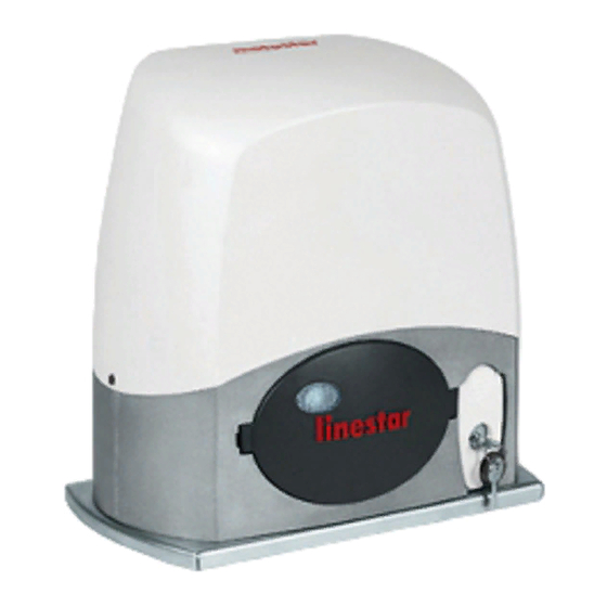
STANDARD SYSTEM DESCRIPTION 1) Flashing lamp with incorporated reception antenna 2) Photoelectric cell 3) Gearmotor 4) Raceway for the electric cables 5) Chain 6) Transmitter Number of wires per cable section: - power supply: 3 x 1.5; - photo-electric cell RX: 4 x 0.5; - photo-electric cell TX: 2 x 0.5;... -
Page 4: General Characteristics
GENERAL CHARACTERISTICS Automation for residential-use sliding gates with IP54 protection, equipped with: - self-learning of the code between transmitter and radio receiver; - adjustable end-stop unit in the automation; - control board positioned horizontally in the upper part of the gearmotor to facilitate electric cablings;... -
Page 5: Unit Assembly
ASSEMBLY OF THE UNIT INSPECTIONS OF THE GATE BEFORE INSTALLATION • • Check that the sliding wheels are effi- The upper guide runners must not cause cient. friction. Sliding wheels Upper guide runners • • The underground guide must be well Check the presence of an mechanical fixed to the ground, completely on the sur- end-stop during opening and closing, or... - Page 6 PREPARING AND FIXING THE ANCHORING PLATE • • Prepare a cavity at a distance (see set- Insert an iron grating to reinforce the ce- tings) from the end of the gate. Prepare the ment and consolidate the anchoring power sheath tubings and accessories in bracket.
- Page 7 • • Resting the fixing plate over the iron grat- Wait for everything to solidify for at least ing, being careful of the sheath tubings that 24 hours. must pass through the holes already drilled on the plate. • • Position the fixing plate at 55 and 220 Remove the box.
- Page 8 FIXING THE CHAIN • • On the gate, mark the distance of 110 Secure the second bracket from the other mm between the anchoring base surface end of the gate, following the procedures and the bracket-securing holes. above. • Secure the chain onto the bracket using the tie rods, nuts, washers and the hooks supplied.
- Page 9 LAYING THE UNIT • • Remove the nuts and the washers from Unscrew the pulley’s four upper-support the gearmotor fixing screws. screws. • • Insert the cables for the electrical con- Position the gearmotor over the anchor- nections into the sheath tubings until they ing bracket with the screws in their slots extend about 400 mm from the tube.
- Page 10 • • The overall-adjustment system is made Insert the pulley support and secure it. up of: - threaded steel feet allow for vertical ad- justment and levelling; Feet - slots, allow for horizontal adjustment. • Secure the gearmotor unit with the wash- ers and nuts to make the unit hitch to the plate in an integral manner.
- Page 11 RELEASING THE GEARMOTOR AND ADJUSTING THE END-STOP UNIT • • Insert the key, turn clockwise and lift the Position the gate at 50 mm from full open- door for release the gearmotor. ing. 50 mm • Move the white cam anticlockwise until the opening microswitch switches and tighten it.
-
Page 12: Description Of The Control Board
DESCRIPTION OF THE CONTROL BOARD The control board is powered at 230V The board has these functions: (AC.) in the L-N terminals and is protected - opening-closure command , button in input with a 1A mains fuse. The control connected to G-Ps or by radio-control, gate devices are low-voltage type, and pro- opening and closing, see dip switches 2 tected with a 3.15mA fuse. -
Page 13: Main Components Of The Control Board
MAIN COMPONENTS OF THE CONTROL BOARD 1 - Terminal board for connecting the 230V (AC.) power supply 2 - Terminal boards for connecting the transformer 3 - Terminal board for connecting signalling accessories 4 - Terminal board for connecting the end-stop unit 5 - Terminal board for connecting the RG58 cable for the antenna 6 - Radiofrequency board for remote control 7 - Trimmer for adjusting partial opening... -
Page 14: Electric Connections
ELECTRIC CONNECTIONS GEARMOTOR, TRANSFORMAR, POWER SUPPLY AND LIMIT SWITCH Orange White Motor Limit switch group (24V d.c.) Orange Viola Green Transformer Black White Power supply 230V (a.c.) - 50/60Hz If assembly has to be on the left, invert the end-stop FA-FC electric wire and M-N motor phases. - Page 15 SIGNALLING AND LIGHTING DEVICES Voltage signalling LED. Green LED indicates that It signals voltage in the electric panel the panel is powered by mains voltage Red LED indicates that the panel is powered with emergency batteries. Flashing lamp (24V-25W), signals, with the intermittent flashing, the gate movement with possibility of pre- flashing while opening and closing...
- Page 16 COMMAND DEVICES Caution: all the contacts and push-buttons normally closed (N.C.) not used, must be disabled by dip-switch or short-circuited. Incorporated Additional reception antenna accessories Pedestrian opening pushbutton for remote radio- power supply N.O. contact, partial opening of the control use. 24V (AC.
- Page 17 SAFETY DEVICES Connecting of a pair of photoelectric cells in re-opening during the gate-closure phase (dip switch 7 OFF and 8 ON). Connection of a pair of photoelectric cells in re-opening during the closure phase and one in partial stop (dip switches 7 and 8 OFF). Photoelectric cells in partial stop Photoelectric cells in re-opening...
- Page 18 Connecting a pair of photoelectric cells in re-opening and in partial stop, with possible connecting of a safety rib in reopening during gate closure and one in re-closing during opening. Safety rib in re-opening, Safety rib in re-closing, N.C. contact. (remove the N.C.
-
Page 19: Check Test For Photoelectric Cells Operation
CHECK TEST OF THE PHOTOELECTRIC CELLS OPERATION Riapertura in fase di Allows the control unit to check chiusura the efficiency of the safety devices (photoelectric cells) at Stop every opening or closure parziale command. To activate this function, move 20 G TX D1 TX T dip switch 10 to ON (see page 23 for the LED signallings). -
Page 20: Function Selections
FUNCTION SELECTIONS Remove the board protection, removing 1 ON Automatic closure; the automatic-clo- the two screws as shown in the figure. sure timer self-powers at the end of the opening movement time. The adjustable pre-set time however depends on the in- tervention of any safety accessories and it is cut out after a “stop”... - Page 21 5 ON Obstacle detection with motor at limit 8 OFF Partial stop (only with connected switch; with motor not running (door closed, photoelectric cells, otherwise leave the dip open or after a total stop command), hin- set to ON). ders any movement if the safety devices If an obstacle is detected during movement, (e.g.
-
Page 22: Adjustments
ADJUSTMENTS Adjust the gate opening, the automatic Trimmer AUTOMATIC CLOSING = Auto- closing or the sensitivity of the motor force, matic closure time. Adjusts the gate’s wait- turning the trimmer + or - using a screw- ing time at while opening before it begins driver as indicated in the figure. -
Page 23: Led Control Functions
LED CONTROL FUNCTIONS YELLOW LED « DIP SWITCH FUNCTION D6» SW1 = Automatic closure SW6 = Manual operation SW2 = Open/Close/Reverse SW7 = Reopening during closing SW3 = Open only SW8 = Partial stop Signals the intervention of SW4 = Preflashing SW9 = Function slowing activated SW5 = Obstacle detection SW10 = Safety test function... -
Page 24: Connection For The Emergency Batteries
Should you require instructions 36210 CHABRIS FRANCE for specific applications not described here, our specialists are available to assist you. Do not hesitate to MOTOSTAR UK contact us by calling our toll-free number. : 0177 3602555 TELEPHONE : 0177 3602844...
Need help?
Do you have a question about the LINESTAR and is the answer not in the manual?
Questions and answers