
Related Manuals for Motostar Stylstar


Summary of Contents for Motostar Stylstar
- Page 1 TION FOR SWING GA TION FOR SWING GA AUT OMA OMA TION FOR SWING GA TION FOR SWING GA TES TION FOR SWING GA STYLST STYLST STYLST AR STYLST STYLST INSTALLATION MANUAL...
-
Page 2: Table Of Contents
CONTENTS Standard system description page 3 Description of the gearmotor unit components page 3 General characteristics page 4 Technical characteristics of the gearmotor page 4 Dimensions of the gearmotor and control panel page 4 Use limits page 5 Installing the unit gearmotor page 5 General characteristics of the control panel page 9... -
Page 3: Standard System Description
STANDARD SYSTEM DESCRIPTION 1)Flashing lamp with incorporated reception antenna 2) Radio keyboard 3) Control panel 4) Photoelectric cell 5) Raceway for electric cables 6) Gearmotors 7) Transmitter Number of wires per cable section: - power supply: 3 x 1,5 - photocellulas RX: 4 x 0,5 - photocellulas TX: 2 x 0,5 - flashing lamp: 2 x 1,5 - gearmotor: 3 x 1,5... -
Page 4: General Characteristics
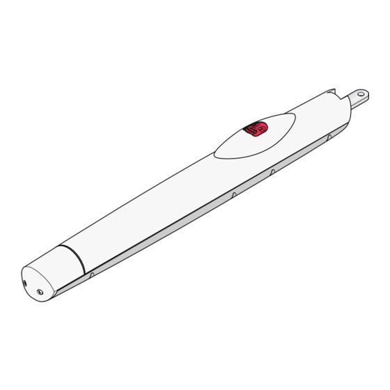
GENERAL CHARACTERISTICS Automation for swing gates up to 2.20 meters per wing with 230V AC power and IP54 protection, equipped with: - self-learning of the code between transmitter and radio receiver; - end-stop unit inserted into the front part of the automation, that manages the wing’s stop during opening and the slowing during closing, with simple adjustments using distance ring (supplied);... -
Page 5: Use Limits
USE LIMITS Max 50 mm Max 2200 mm Max 300 Kg Position the bracket flush with the pillar 710 mm INSTALLING THE GEARMOTOR UNIT INSPECTING THE GATE BEFORE INSTALLATION • • Check that the frame of the gate is robust That there is a mechanical stop block for closing and opening (fixed well to the enough and that the hinges are efficient. - Page 6 PREPARING THE SHEATH TUBINGS, CONNECTOR BLOCKS WITH AND BRACKET ASSEMBLY. • • Prepare the tubes for the electrical con- Secure the tail bracket to the pillar using nections and install connector blocks on suitable fixing accessories chosen de- both sides of the gate. pending on the shape of the fixing mate- rial.
- Page 7 FIXING THE GEARMOTOR UNIT • • Secure the rear part of the gearmotor with Move the door, insert the three-lobed key screws, bushing (lubricated), washer and and turn it clockwise to release the nut on the tail bracket. gearmotor. • •...
- Page 8 ADJUSTING THE END-STOP UNIT • • Remove the dome of the end-stop unit Position the gate in the full-open posi- with a screwdriver. tion, move the opening cam until the microswitch switches and fix it. • • Before starting with the adjustments, Position the gate at the limit switch posi- check the length of each individual wing.
-
Page 9: General Characteristics Of The Control Panel
GENERAL CHARACTERISTICS OF THE ELECTRIC PANEL Container made of ABS with IP54 protection, complete with control board, radio receiver and transformer. The container unit requires some specific assembly operations. ASSEMBLING AND FIXING THE ELECTRIC PANEL • • Assemble the spring-type hinges found Position and secure the housing using in the pack. -
Page 10: Description Of The Control Board
DESCRIPTION OF THE CONTROL BOARD The control panel is powered with a 230V The board’s functions are: (AC.) voltage in the terminals L-N and is - opening-closure command , pushbutton protected in input with a 1A mains fuse. connected to G-Ps or by radio-control, gate The control devices are a low-voltage type opening and closing, see dip switch 2 and and protected with a 315mA fuse. -
Page 11: Main Components Of The Control Board
MAIN COMPONENTS OF THE ELECTRIC PANEL 1 - Transformer 2 - 315mA control unit fuse 3 - Trimmer for adjusting automatic closing time 4 - Terminal board to connect the transformer 5 - Trimmer for adjusting sensitivity to obstacles 6 - Trimmer for adjusting the 2nd motor’s closure time 7 - Buttons for memorizing the radio code 8 - Functions control LED 9 - “Dip-switch”... -
Page 12: Electrical Connections
ELECTRICAL CONNECTIONS GEARMOTORS, TRANSFORMER AND POWER SUPPLY Transformer CONTROL BOARD FUSE 315 mA + DELAY 2M. - + AUTOM. CLOSING - ALIM PROG ACCES. FUSE 1,6A LINE FUSE 1A Motor 2 (24V Blue Black d.c.), delayed Brown during closure Blue Black Brown Neutral... - Page 13 ALIM PROG CONTROL DEVICES Reception antenna Powering incorporated into the further flashing lamp for using accessories the remote radio- 24V (AC. - DC.), control max 4W. + + + ST G B1 B2 Cable RG58 «Stop» pushbutton N.C. contact.( remove the bridge wire ).
- Page 14 1,6A DEVICES OF NOTIFICATION AND ILLUMINATION 20 K1 K5 Pilot lamp (24V-3W), remains on to indicate «gate open». 630mA FA FC F FA FC F Flashing lamp (24V-25W), signals gate movement with the intermittent + SENS. - + DELAY 2M. - + AUTOM.
-
Page 15: Check Test For Operating The Photoelectric Cells
FA FC F 630mA + SENS. - + DELAY 2M. - + AUTOM. CLOSING - CHECK TEST FOR OPERATING THE PHOTOELECTRIC CELLS Allows the control unit to LED «D1 or D3» operation ALIM PROG check the efficiency of the notification of the photoelectric cells safety devices (photoelectric cells) at every open or close DIP «9»Activating the... -
Page 16: Function Selections
FUNCTION SELECTIONS Select the functions by setting the dip 2 ON - 3 OFF Command type “Open-stop- switches to ON or OFF with a screwdriver, close-stop” with pushbutton (G-Ps) and as indicated in the figure. transmitter; By default, dip switches 7 and 8 are set to 2 OFF - 3OFF Command type “Open-close”... - Page 17 6 ON “Maintained Action”, gate operation 8 OFF Partial stop (only with photoelectric keeping the pushbutton pressed; this cells connected, otherwise leave the dip set to ON). function excludes use of the remote control ; If an obstacle is detected during movement, the gate stops.
-
Page 18: Functions Adjustments
FUNCTION ADJUSTMENTS Adjust the gate opening, the automatic AUTOMATIC CLOSING Trimmer = Auto- closing or the sensitivity of the motor matic closure time. Adjusts the gate’s wait- power, by turning the trimmer + or -, using ing time while opening before it starts to a screwdriver as shown in the figure. -
Page 19: Adjusting The Limit Switch
CHECK ON THE ADJUSTMENT OF THE LIMIT SWITCH • • Press the button from the transmitter to When closure is complete, check that the open the gate. The LED of every end-stop red LED comes on; if the gate reverses its unit will remain on until the wings are fully movement, repeat adjustment of the cam open. -
Page 20: Led Control Functions
LED CONTROL FUNCTIONS YELLOW LED « ST» Comes on every time the total ALIM ALIM PROG PROG D1 D1 D3 D3 ST ST stop button is pressed. ST - G YELLOW LED « YELLOW LED « GREEN LED « RED LED « D1»...
Need help?
Do you have a question about the Stylstar and is the answer not in the manual?
Questions and answers