Table of Contents
Advertisement
Quick Links
Advertisement
Table of Contents

Related Manuals for Motorvac CarbonClean MCS 245


Summary of Contents for Motorvac CarbonClean MCS 245
- Page 1 Fuel System Service & Diagnostic Equipment OPERATOR’S MANUAL MCS 245 PDF VERSION...
-
Page 2: Table Of Contents
Table of Contents Introduction ....................Error! Bookmark not defined. Overview ....................Error! Bookmark not defined. System Features and Functions ......................1-1 System Features and Functions....................1-2 Hose and Battery Connections......................1-3 Fuel Filter............................1-5 Theory of Operation………………………………………………………………………………………1-6 Safety Information ..........................2-1 Before You Begin..........................3-1 First Time Operation........................3-1 Mixing Ratio...........................3-2 Fuel System Cleaning Procedures....................4-1 Determining the Vehicle's Fuel System Type................4-1... -
Page 3: System Features And Functions
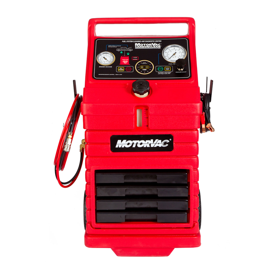
System Features and Functions The front of the cabinet contains a software-driven control panel, the opening MotorVac CarbonClean System for the fuel reservoir, and storage drawers for adaptors and other system accessories. TIME DISPLAY, CYCLE COMPLETE LED & TIMER BUTTONS... - Page 4 System Features and Functions Descriptions of the gauges, control buttons, and LED indicators that make up the control panel are listed below. Please become familiar with these control panel features and functions before using the unit Stop Button Stops all run conditions. Fill/Purge Button Fill: Transfers fuel from the fuel tank of the vehicle being serviced to the unit’s reservoir.
- Page 5 FRONT VIEW FUEL LEVEL WINDOW...
- Page 6 LEFT VIEW As you face the system, the left side of the unit’s cabinet holds the fuel return and output hoses, while the right side of the unit’s cabinet holds the battery cables and vacuum pressure hose. Output Hose (red) Connects to the input side of the vehicle's engine fuel system.
- Page 7 RIGHT VIEW Vacuum Hose Forms a connection between the vacuum pressure from the vehicle engine and the vacuum pressure gauge on the unit. Battery Cables Positive (red) and negative (black) battery connections (12-16 VOLTS DC and 8 AMPERES)
- Page 8 BACK VIEW The back of the unit’s cabinet contains an easy access area for the fuel filter, along with storage slots for shop towels, detergent bottles, etc. Please see for information on replacing the unit’s fuel filter. Appendix A...
-
Page 9: Theory Of Operation
Theory of Operations Detailed descriptions of the various operations, control buttons, and LED indicators are listed below. Fill Operation: • Press and Hold the FILL/PURGE button. This opens the solenoid and starts the pump motor in the Fill/Purge direction. Releasing the button stops the motor and closes the solenoid. •... - Page 10 Pressure Switch Operation: • The pressure switch is opened when the pressure is less than 4 PSI and is closed when the pressure is 4 PSI or greater. • The internal pressure switch is not adjustable. Solenoid Operation: • The solenoid opens when the pump motor is running in either fill/purge or cleaning (service) mode. Note: The solenoid is normally closed.
-
Page 11: Safety Information
Safety Information and Precautions /!\ DANGER Vehicle exhaust gases contain Carbon Monoxide, which is a colorless and odorless lethal gas. Only run engines in well-ventilated areas and avoid breathing exhaust gases. Extended breathing of exhaust gases will cause serious injury or death. /!\ WARNING Exhaust gases, moving parts, hot surfaces, and potent chemicals are present during the use of the fuel system cleaner. - Page 12 Moving vehicles can cause injury. Moving engine parts. The engine cooling fan will cycle on and off depending on the coolant temperature and could operate without the engine running. Wear safety goggles. Always keep objects, clothing, and hands away from the cooling fans and engine parts. Moving engine parts can cause injury.
-
Page 13: Before You Begin
Before You Begin First Time Operation NOTE The following process is used to flush factory testing fluids out of your new machine, and is only necessary before the first time you use the unit. Remember to send in your warranty card to properly register your machine. - Page 14 The unit’s reservoir is now completely drained of fuel. Follow the steps below before performing the first cleaning service: • If necessary, Repeat Steps 3-4 from the previous page. • Pour 20 oz. of detergent to the unit’s reservoir. • Add clean gasoline to the unit’s fuel reservoir until the mixture of fuel and detergent reaches 1/4 tank according to the Fuel Level Window.
-
Page 15: Fuel System Cleaning Procedures
Fuel System Cleaning Procedures Determining the Vehicle's Fuel System Type It is very important to determine the fuel system type of the vehicle to be serviced before performing any setup or cleaning procedure on the vehicle. The unit can be used with any of the four different types of fuel systems listed below: Carburetion Carburetors come in a variety of sizes and shapes. -
Page 16: Carburetor Setup Procedure
Carburetor Setup Procedure Follow the steps below to connect the unit to the vehicle's fuel system in order to obtain fuel from the vehicle for use during the cleaning procedure. Make sure the vehicle has at least 1/8 tank of fuel before beginning this process. Start the vehicle and allow the engine to reach normal operating temperature IMPORTANT Do not perform the setup or cleaning process if the... - Page 17 As shown below, connect the appropriate adaptors at the two points listed in Step 7. RED HOSE BLACK HOSE PRESSURE LINE ADAPTOR CARBURETOR 060-4500 " T " FUEL TANK ADAPTOR FUEL PUMP As shown in the previous figure, attach the ends of the T-adaptor (#060-4500) to both adaptors, and then attach the output ( ) hose to the center connection on the T- adaptor.
- Page 18 NOTE If the vehicle’s engine stalls, restrict pressure in the fuel line by turning the gate valve on the T-adaptor (#060- 4500) clockwise 1/4 turn. Re-start the car and repeat Step 12. If the vehicle’s engine stalls again, repeat this procedure until Step 12 is completed.
- Page 19 As shown in the next figure, disconnect the female end of the T-adaptor (#060-4500) from the carburetor and connect it to itself at the male fitting. This stops the flow of fuel from the vehicle to the carburetor during the cleaning process. BLACK HOSE RED HOSE ADAPTOR...
-
Page 20: Carburetor Cleaning Procedure
Carburetor Cleaning Procedure Follow the steps below to circulate the fuel/detergent mixture through the vehicle's carburetor. Verify that above have been completed. Carburetor Setup Steps 1-18 Refer to the vehicle's service manual for the manufacturer's recommended PSI. • At this point, refer to appropriate Intake System Cleaning Procedure section for proper intake cleaning, and Vacuum gauge connections in the vehicle diagnostics chapter. - Page 21 IMPORTANT Wrap a shop towel around pressure fittings before disconnection to protect against residual fuel spray. Disconnect the battery leads, hoses, and adaptors. Return the vehicle's fuel system to its normal operating condition by re-connecting the vehicle's fuel lines. and verify that there are no leaks. 13.
-
Page 22: Throttle Body Injection (Tbi) Setup Procedure
Throttle Body Injection (TBI) Setup Procedure Follow the steps below to connect the unit to the vehicle's fuel system in order to obtain fuel from the vehicle for use during the cleaning procedure. Make sure the vehicle has at least 1/8 tank of fuel before beginning this process. Start the vehicle and allow the engine to reach normal operating temperature IMPORTANT Do not perform the setup or cleaning process if the... - Page 23 As shown in the next figure, connect the appropriate adaptors at the points listed in Step 7 BLACK HOSE RED HOSE ADAPTOR PRESSURE LINE FILTER 060-4500 " T " THROTTLE BODY UNIT ADAPTOR ADAPTOR RETURN LINE ADAPTOR 060-2501 FUEL TANK "LOOP"...
- Page 24 When filling the reservoir, add 8 oz. of detergent first for every 1/4 tank of fuel added. Press and hold the button on the control panel until the Fill/Purge Fuel Level indicates a combined increase of 1/4 tank in the unit’s fuel reservoir. Window NOTE If the vehicle’s engine stalls, restrict pressure in the fuel...
- Page 25 As shown in the next figure, connect one end of the loop adaptor (#060-2501) to the pressure line coming from the vehicle's fuel tank. Connect the other end of the loop adaptor (#060-2501) to the return line going back to the fuel tank. This forms a tank- to-tank loop, making it unnecessary to disconnect the fuel pump.
-
Page 26: Throttle Body Injection (Tbi) Cleaning Procedure
Throttle Body Injection (TBI) Cleaning Procedure Follow these steps to circulate the cleaning mixture through the TBI unit to clean the throttle body, injector screens, and pressure regulator. Verify that above have been completed before continuing TBI Setup Steps 1-18 Refer to the vehicle's service manual for the manufacturer's recommended PSI. - Page 27 When the run time expires, the cleaning is complete. The unit will automatically shut off and purge the pressure lines for five seconds. The LED on the Cycle Complete control panel will illuminate, and the unit’s alarm will sound. 11. Turn OFF the vehicle's ignition. Turn the regulator counterclockwise on the unit to open it.
-
Page 28: Port Fuel Injection (Pfi) Setup Procedure
Port Fuel Injection (PFI) Setup Procedure Follow the steps below to connect the unit to the vehicle's fuel system in order to obtain fuel from the vehicle for use during the cleaning procedure. Make sure the vehicle has at least 1/8 tank of fuel before beginning this process. Start the vehicle and allow the engine to reach normal operating temperature IMPORTANT Do not perform the setup or cleaning process if the... - Page 29 As shown in the next figure, connect the appropriate adaptors at the points listed in Step 7 As shown in the previous figure, attach the T-adaptor (#060-4500) and the loop adaptor (#060-2501) as follows: • Attach the ends of the T-adaptor (#060-4500) to both pressure line adaptors, then attach the output (red) hose to the center connection on the T-adaptor.
- Page 30 When filling the reservoir, add 8 oz. of detergent first for every 1/4 tank of fuel added. Press and hold the button on the control panel until the Fill/Purge Fuel Level indicates a combined increase of 1/4 tank in the unit’s fuel reservoir. Window NOTE If the vehicle’s engine stalls, restrict pressure in the fuel...
- Page 31 As shown in the next figure, connect one end of the loop adaptor (#060-2501) to the pressure line coming from the vehicle's fuel tank. Connect the other end of the loop adaptor (#060-2501) to the return line going back to the fuel tank. This forms a tank- to-tank loop, making it unnecessary to disconnect the fuel pump.
-
Page 32: Port Fuel Injection (Pfi) Cleaning Procedure
Port Fuel Injection (PFI) Cleaning Procedure Follow these steps to circulate the cleaning mixture through the Port Fuel Injection unit to clean the fuel rail, injector screens, and pressure regulator. Verify that above have been completed before continuing PFI Setup Steps 1-18 Refer to the vehicle's service manual for the manufacturer's recommended PSI. - Page 33 When the run time expires, the cleaning is complete. The unit will automatically shut off and purge the pressure lines for five seconds. The LED on the Cycle Complete control panel will illuminate, and the unit’s alarm will sound. 11. Turn OFF the vehicle's ignition. Turn the regulator counterclockwise on the unit to open it.
-
Page 34: Continuous Injection System (Cis) Setup Procedure
Continuous Injection System (CIS) Setup Procedure Follow the steps below to connect the unit to the vehicle's fuel system in order to obtain fuel from the vehicle for use during the cleaning procedure. Make sure the vehicle has at least 1/8 tank of fuel before beginning this process. Start the vehicle and allow the engine to reach normal operating temperature IMPORTANT Do not perform the setup or cleaning process if the vehicle’s... - Page 35 As shown in the next figure, connect the appropriate adaptors at the points listed in Step 7 As shown in the previous figure, attach the T-adaptor (#060-4500) and the loop adaptor (#060-2501) as follows: • Attach the ends of the T-adaptor (#060-4500) to both pressure line adaptors, then attach the output ) hose to the center connection on the T-adaptor.
- Page 36 When filling the reservoir, add 8 oz. of detergent for every 1/4 tank of fuel. Press and hold the button on the control panel until the Fill/Purge Fuel Level indicates a combined increase of 1/4 tank in the unit’s fuel reservoir. Window NOTE If the vehicle’s engine stalls, restrict pressure in the fuel...
- Page 37 As shown in the next figure, connect one end of the loop adaptor (#060-2501) to the pressure line coming from the vehicle's fuel tank. Connect the other end of the loop adaptor (#060-2501) to the return line going back to the fuel tank. This forms a tank- to-tank loop, making it unnecessary to disconnect the fuel pump.
-
Page 38: Continuous Injection System (Cis) Cleaning Procedure
Continuous Injection System (CIS) Cleaning Procedure Follow the steps below to circulate the cleaning mixture through the CIS fuel distributor to clean the pressure regulator and the top portion of the fuel distributor. Verify that above have been completed before continuing. CIS Setup Steps 1-18 •... - Page 39 Press the button to increases the time, or the ▬ button to decreases the time until LED display indicates 30 minutes. (Run time may be adjusted depending on Time the condition of the vehicle’s fuel system.) to begin the fuel system cleaning process. 9.
-
Page 40: Returnless System Setup Procedure
Returnless Fuel System Setup Procedure Follow the steps below to connect the unit to the vehicle's fuel system. Make sure the vehicle has at least 1/8 tank of fuel before beginning this process. IMPORTANT Do not perform the setup or cleaning process if the vehicle's engine oil or coolant level is low. - Page 41 Returnless System Cleaning Diagram Note: To perform a leak down check, verify the vehicles fuel pump pressure, and/or fill the unit’s reservoir; connect the TEE adaptor 060-4500 inline between the fuel rail and fuel pressure line from tank. The unit’s RED output hose would connect to the ball valve of the TEE adaptor. The BLACK return line is not used at this time.
-
Page 42: Returnless System Cleaning Procedure
Returnless System Cleaning Procedure Follow the steps below to feed the fuel/detergent mixture into the vehicle's fuel injector system. Verify that the Returnless System Setup Steps 1- 8 above have been completed. NOTE: The rail flush procedure is not performed on a Returnless System. Refer to the vehicle's service manual for the manufacturer's recommended PSI. - Page 43 IMPORTANT Close the gate valve on the T-adaptor and wrap a shop towel around pressure fittings before disconnection to protect against residual fuel spray. Disconnect the battery leads, hoses, and adaptors. Return the vehicle's fuel system to its normal operating condition by re-connecting the vehicle's fuel lines. and verify that there are no leaks.
-
Page 44: Vehicle Diagnostics
Vehicle Diagnostics Although vehicle diagnostic tests are not a mandatory part of the cleaning procedure, they can help determine if poor engine performance is caused by other conditions related to the fuel system. Carburetors The following tests may be performed for this system: •... -
Page 45: Fuel System Pressure Test
Fuel System Pressure Test 1. Verify that Setup Steps 1-10 from the appropriate previous chapter have been completed for the specific fuel system type to be tested Verify that the vehicle’s engine is running and check connections for leaks. Note the vehicle’s fuel system pressure reading from the gauge on the Fuel Pressure control panel of the unit. -
Page 46: Fuel Volume Test
Fuel Volume Test 1. Verify that Setup Steps 1-10 from the appropriate previous chapter have been completed for the specific fuel system type to be tested Verify that the vehicle’s engine is running and check connections for leaks. Press and hold the button. -
Page 47: Deadhead Test
Deadhead Test Do NOT perform the Deadhead test on CIS vehicles. 1. Verify that Setup Steps 1-10 from the appropriate previous chapter have been completed for the specific fuel system type to be tested Verify that the vehicle’s engine is running and check connections for leaks. Bend the loop adaptor (#060-2501) in half for one second to restrict pressure and then release it. -
Page 48: Leakdown Test
Leakdown Test 1. Verify that Setup Steps 1-10 from the appropriate previous chapter have been completed for the specific fuel system type to be tested Verify that the vehicle’s engine is running and check connections for leaks. Turn off the vehicle. Note the pressure reading on the unit’s gauge. -
Page 49: Vacuum Pressure Test
MotorVac CarbonClean System diagnostic equipment. The readings on the gauge should indicate a substantial Vacuum Pressure improvement in the engine performance after the cleaning process is complete. -
Page 50: Intake System Cleaning Procedures
Warm up vehicle to operating temperature. Shut off vehicle. Fill the ICS container with a MAXIMUM of 4 ounces of MotorVac detergent. ( See page B-10 in Appendix B for ICS kit breaksown .) Pressurize the container with shop air to a minimum of 80 PSI. Do not exceed 185 PSI. - Page 51 NOTE: Do not spray outside of the throttle bore housing. If the MotorVac CarbonClean System is in use at the time, press the STOP button or Turn the timer knob to the zero position to depressurize the engine’s fuel system.
- Page 52 The continuation of the cleaning service will require the installation of the 6-inch spray tube to clean the Idle Air Control passage while the engine is running. NOTE: If you do not understand these instructions completely or have any questions contact MotorVac Technical support at 800-841-8810 BEFORE performing this procedure.
- Page 53 Throttle Body and Carburetor Systems Warm up vehicle to operating temperature. Shut off vehicle and remove air cleaner. Open the ICS Spray Bottle and add 4 oz. of intake cleaning detergent. Pressurize with shop air and insert the short (6”) Spray Tube into the Nozzle. IMPORTANT DO NOT EXCEED 185 PSI USE SAFETY GLASSES...
- Page 54 Cleaning Through a Vacuum Port for Added Carbon Removal Capabilities Warm up vehicle to operating temperature. Open the ICS Spray Bottle and add 8 oz. of intake cleaning detergent. Pressurize with shop air and insert the short (6”) Spray Tube into the Nozzle. IMPORTANT DO NOT EXCEED 185 PSI USE SAFETY GLASSES...
-
Page 55: Troubleshooting And Additional Help
Troubleshooting and Additional Help Refer to the list below in the unlikely event that you have problems with your MotorVac CarbonClean System. Problem: Solution: 1. Reverse Polarity LED is ON and the unit Polarity is reversed on vehicle battery is not operational. -
Page 56: Maintenance Procedures
Maintenance Procedures The following maintenance procedures should be performed on a routine basis: Drain the unit’s fuel reservoir and replace the fuel filter after every 30 cleaning services, as described in the next section. Clean the exterior with a plastics cleaning agent or similar product to keep the cabinet looking new. Check the cabinet for dents or impact markings. -
Page 57: Maintenance Record
Lightly grease the seal of the new filter and hand-tighten it onto the mounting head. Add 16 ozs. of to the fuel reservoir and MotorVac CarbonClean Detergent and Top Engine Cleaner then fill the unit’s fuel reservoir with until the Fuel Level Window indicates 1/4 tank. -
Page 58: Appendix B - System Accessories
FEMALE. (USE WITH SUITABLE 060-1500 HOSE CLAMPS.) CARBURETED VEHICLES WITH 5/16" FLARE FUEL INLETS. USE WITH 060-3304 FOR SOME FUEL INJECTED VEHICLES - 060-1700 RETURN LINE. CARBURETED AND EARLY FUEL INJECTED VEHICLES WITH 3/8" FLARE FUEL INLETS. 060-1800 2005 MotorVac Technologies, Inc. - Page 59 PORT FUEL-RETURN LINE. (USE AS PRESSURE LINE ON SOME RANGERS AND BRONCOS) 080-3402 (O-Ring) 060-3500 080-3501 (Clip) 3/8" FEMALE SPRING LOCK. PORT FUEL - RETURN LINE. (USE AS PRESSURE LINE ON 060-3505 SOME RANGERS AND BRONCOS) 2005 MotorVac Technologies, Inc.
- Page 60 060-3605 3/8" QUICK DISCONNECT PORT FUEL AND TBI 060-3901 080-3904 (Clip) 5/16" MALE TBI AND/OR PORT FUEL (GM-CHRYSLER-JEEP/EAGLE). 060-4200 3/8" TBI AND/OR PORT FUEL (GM-CHRYSLER-JEEP/EAGLE- FORD). 060-4300 1/4" FEMALE TBI AND/OR PORT FUEL (GM-CHRYSLER-JEEP/EAGLE- FORD). 060-3902 2005 MotorVac Technologies, Inc.
- Page 61 Appendix B - System Accessories Tee Adaptor For Single Line Fuel Injection Systems 060-4501 HOSE CLAMPS. USE WITH 060- 1000 THROUGH 060-1500. 060-0440 060-0450 2005 MotorVac Technologies, Inc.
-
Page 62: Deluxe Adaptor Kit
"TEST PORT/SCHRADER VALVE" CONNECTION - FORD. NOTE: THE SCHRADER VALVE CORE MUST BE REMOVED. 060-3508 "TEST PORT/SCHRADER VALVE" CONNECTION - GM. 060-3700 080-3701 (Viton Seal) 5/16" QUICK DISCONNECT PORT FUEL AND TBI FORD 5 LITER 060-3900 080-3903 (Clip) 2005 MotorVac Technologies, Inc. - Page 63 TBI AND/OR PORT FUEL (GM-CHRYSLER-JEEP/EAGLE). 060-4300 CONNECTS 12MM BANJO FITTINGS FOR DIAGNOSTICS AND/OR CREATING A LOOP. 060-1900 060-1901 060-1902 (Bolt) (Washer) (Nut) CONNECTS 14MM BANJO FITTINGS FOR DIAGNOSTICS AND/OR CREATING A LOOP 060-2740 060-2741 060-2742 (Bolt) (Washer) (Nut) 2005 MotorVac Technologies, Inc.
- Page 64 New / Optional GAS Adapters offered by MotorVac The following GAS adapters have been added to the CarbonClean adaptor line-up. The adapters listed are not included with any configured adapter sets & may be purchased separately from MotorVac Technologies, Inc. PART & NO.
- Page 65 CIS SYSTEMS, MERCEDES, AUDI A-6 060-2300 19MM WRENCH SIZE WITH 16MM THREADS - EUROPEAN CARS INLET AND/OR RETURN. MAY BE USED WITH 060-2700. 060-2600 14MM X 16MM UNION. USE IN CONJUNCTION WITH 060-2300 AND 060-2600 060-2700 FOR CIS APPLICATIONS. 2005 MotorVac Technologies, Inc.
- Page 66 30” Wands with Nozzles pack of 10 order #200-5044. 6” Straws with nozzles pack of 10 order #200-5043 This “update” Bottle neck assembly. list effective as of 7/10/2006. # 200-5034 includes air filler housing & base o- ring. 2005 MotorVac Technologies, Inc.
-
Page 67: Appendix C - Parts
Appendix C - Parts Service Parts for the MotorVac MCS 245 CarbonClean System Please refer to the part numbers below when ordering parts for the unit. Part # Description 010-0027 Wheel 010-6060 Reservoir Cap 020-8043 Harness, Power 030-0193 3/8”Compression Nut, Ni (Hose to Machine) - Page 68 200-8300 Quick Reference Cards 200-3025A Standard Adaptor Kit 200-3026A Deluxe Adaptor Kit ORDERING PARTS Parts for the unit may be ordered by calling Customer Service, have your model and serial numbers available: In the U.S. call: (714-558-4822, 800-841-8810) E-MAIL: techsupport@motorvac.com...
Need help?
Do you have a question about the CarbonClean MCS 245 and is the answer not in the manual?
Questions and answers