Table of Contents
Advertisement
Quick Links
Advertisement
Table of Contents

Related Manuals for Motorvac CARBONCLEAN MCS 245


Summary of Contents for Motorvac CARBONCLEAN MCS 245
- Page 1 Fuel System Service & Diagnostic Equipment OPERATOR’S MANUAL MCS 245...
-
Page 2: Table Of Contents
Table of Contents Introduction ............................3 Overview ..............................4 System Features and Functions ......................5 System Features and Functions ......................Hose and Battery Connections ......................Fuel Filter ............................Theory of Operation……………………………………………………………………………………… Safety Information ..........................13 Before You Begin..........................17 First Time Operation........................... Mixing Ratio............................ -
Page 3: Introduction
The MotorVac CarbonClean System is a self-contained cleaning system, designed to connect to any gasoline engine. Once the unit is connected, it temporarily replaces the regular fuel supply with a mixture of gasoline and the specially formulated MotorVac CarbonClean Detergent and Top Engine Cleaner With the engine idling, the unit pumps the gasoline/detergent mixture through the engine's fuel system. -
Page 4: Overview
Overview This manual contains all the information you need to use the MotorVac CarbonClean System. Please make sure all technicians using the unit read this manual and have it within easy reach whenever the unit is being used. The following is a quick reference to the information in this manual: System Features and Functions This chapter describes the MotorVac CarbonClean System gauges, control buttons, LED’s, and... -
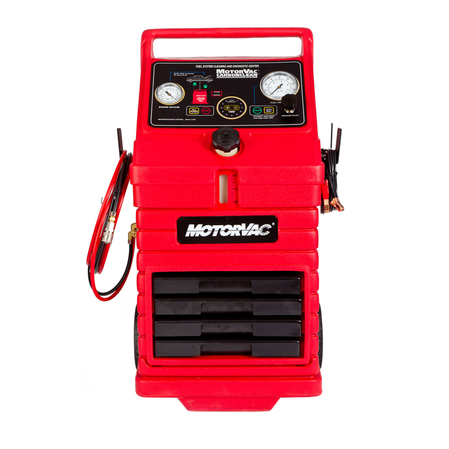
Page 5: System Features And Functions
System Features and Functions The front of the cabinet contains a software-driven control panel, the MotorVac CarbonClean System opening for the fuel reservoir, and storage drawers for adaptors and other system accessories. REVERSE POLARITY LED TIME DISPLAY, CYCLE COMPLETE LED & TIMER BUTTONS... - Page 6 System Features and Functions Descriptions of the gauges, control buttons, and LED indicators that make up the control panel are listed below. Please become familiar with these control panel features and functions before using the unit Stop Button Stops all run conditions. Fill/Purge Button Fill: Transfers fuel from the fuel tank of the vehicle being serviced to the unit’s reservoir.
-
Page 7: Hose And Battery Connections
Hose and Battery Connections As you face the system, the left side of the unit’s cabinet holds the fuel return and output hoses, while the right side of the unit’s cabinet holds the battery cables and vacuum pressure hose. Serial ID Plate Support Hanger Output Hose Return Hose... - Page 8 Support Hanger Support Hanger Vacuum Hose Battery Cables Red (pos) Black (neg) Vacuum Hose Forms a connection between the vacuum pressure from the vehicle engine and the vacuum pressure gauge on the unit. Battery Cables Positive (red) and negative (black) battery connections (8-16 VOLTS DC and 8 AMPERES)
-
Page 9: Fuel Filter
Fuel Filter The back of the unit’s cabinet contains an easy access area for the fuel filter, along with storage slots for shop towels, detergent bottles, etc. Please see for information on replacing the unit’s fuel filter. Appendix A A ir V e n ts S ys te m F ilte r A ir V e n ts W h e e ls... -
Page 10: Theory Of Operation
Theory of Operations Detailed descriptions of the various operations, control buttons, and LED indicators are listed below. Fill Operation: • When the FILL/PURGE button is pressed and held the solenoid opens and the motor starts the pump in the Fill/Purge direction. Releasing the button stops the motor and closes the solenoid. •... - Page 11 Pressure Switch Operation: • The pressure switch is opened when the pressure is less than 4 PSI and is closed when the pressure is 4 PSI or greater. Solenoid Operation: • The solenoid is only opened when the motor is running in either fill or cleaning (run) directions. Stop Operation: •...
- Page 12 Notes:...
-
Page 13: Safety Information
Safety Information and Precautions /!\ DANGER Vehicle exhaust gases contain Carbon Monoxide, which is a colorless and odorless lethal gas. Only run engines in well-ventilated areas and avoid breathing exhaust gases. Extended breathing of exhaust gases will cause serious injury or death. /!\ WARNING Exhaust gases, moving parts, hot surfaces, and potent chemicals are present during the use of the fuel system cleaner. - Page 14 Chemicals can cause harmful byproducts. Use only approved chemicals (refer to operator’s manual). Do not swallow or ingest any chemicals. Use with adequate ventilation. Avoid breathing vapors. Do not store chemicals on the machine. Improper use of chemicals can cause injury. Over exposure can have harmful effect on eyes, skin, respiratory system and possible unconsciousness and asphyxiation.
- Page 15 Keep sparks and flames away from the battery and never lay tools, equipment, or other conductive objects on the battery. When tools or equipment is connected to the battery, make sure the equipment power switch is off. Connect the positive lead of the equipment to the positive lead battery first; connect the negative lead of the equipment to a solid ground point as far from the battery as possible.
- Page 16 Notes:...
-
Page 17: Before You Begin
Before You Begin First Time Operation NOTE The following process is used to flush factory testing fluids out of your new machine, and is only necessary before the first time you use the unit. Remember to send in your warranty card to properly register your machine. - Page 18 Connect the #060-1100 adaptor to the output hose, then drain the gasoline from the unit’s reservoir using the following procedure: • Direct the adaptor and output (red) hose into an appropriate container. • Press and hold the Start button until the fuel from the unit has been emptied. •...
-
Page 19: Fuel System Cleaning Procedures
Fuel System Cleaning Procedures Determining the Vehicle's Fuel System Type It is very important to determine the fuel system type of the vehicle to be serviced before performing any setup or cleaning procedure on the vehicle. The unit can be used with any of the four different types of fuel systems listed below: Carburetion Carburetors come in a variety of sizes and shapes. - Page 20 Notes:...
-
Page 21: Carburetor Setup Procedure
Carburetor Setup Procedure Follow the steps below to connect the unit to the vehicle's fuel system in order to obtain fuel from the vehicle for use during the cleaning procedure. Make sure the vehicle has at least 1/8 tank of fuel before beginning this process. Start the vehicle and allow the engine to reach normal operating temperature IMPORTANT Do not perform the setup or cleaning process if the... - Page 22 As shown below, connect the appropriate adaptors at the two points listed in Step 7. BLACK HOSE RED HOSE PRESSURE LINE ADAPTOR CARBURETOR 060-4500 " T " FUEL TANK ADAPTOR FUEL PUMP As shown in the previous figure, attach the ends of the T-adaptor (#060-4500) to both adaptors, then attach the output ( ) hose to the center connection on the T-adaptor.
- Page 23 NOTE If the vehicle’s engine stalls, restrict pressure in the fuel line by turning the gate valve on the T-adaptor (#060-4500) clockwise 1/4 turn. Re-start the car and repeat Step 12. If the vehicle’s engine stalls again, repeat this procedure until Step 12 is completed. 13.
- Page 24 As shown in the next figure, disconnect the female end of the T-adaptor (#060-4500) from the carburetor and connect it to itself at the male fitting. This stops the flow of fuel from the vehicle to the carburetor during the cleaning process. BLACK HOSE RED HOSE ADAPTOR...
-
Page 25: Carburetor Cleaning Procedure
Carburetor Cleaning Procedure Follow the steps below to circulate the fuel/detergent mixture through the vehicle's carburetor. Verify that above have been completed. Carburetor Setup Steps 1-18 Refer to the vehicle's service manual for the manufacturer's recommended PSI. • Refer to appropriate Intake System Cleaning Procedure chapter for system cleaning at this point, and Vacuum gauge connections in the vehicle diagnostics chapter. - Page 26 IMPORTANT Close the gate valve on the T-adaptor and wrap a shop towel around pressure fittings before disconnection to protect against residual fuel spray. Disconnect the battery leads, hoses, and adaptors. Return the vehicle's fuel system to its normal operating condition by re-connecting the vehicle's fuel lines. Re-install the vehicle's gas cap.
- Page 27 Throttle Body Injection (TBI) Setup Proce dure Follow the steps below to connect the unit to the vehicle's fuel system in order to obtain fuel from the vehicle for use during the cleaning procedure. Make sure the vehicle has at least 1/8 tank of fuel before beginning this process. Start the vehicle and allow the engine to reach normal operating temperature IMPORTANT Do not perform the setup or cleaning process if the...
- Page 28 As shown in the next figure, connect the appropriate adaptors at the points listed in Step 7 BLACK HOSE RED HOSE ADAPTOR PRESSURE LINE FILTER 060-4500 " T " THROTTLE BODY UNIT ADAPTOR ADAPTOR RETURN LINE ADAPTOR 060-2501 FUEL TANK "LOOP"...
- Page 29 When filling the reservoir, add 8 oz. of detergent for every 1/4 tank of fuel. Press and hold the button on the control panel until the indicates a Fill/Purge Fuel Level Window combined increase of 1/4 tank in the unit’s fuel reservoir. NOTE If the vehicle’s engine stalls, restrict pressure in the fuel line by turning the gate valve on the T-adaptor...
- Page 30 As shown in the next figure, connect one end of the loop adaptor (#060-2501) to the pressure line coming from the vehicle's fuel tank. Connect the other end of the loop adaptor (#060-2501) to the return line going back to the fuel tank. This forms a tank-to-tank loop, making it unnecessary to disconnect the fuel pump.
-
Page 31: Throttle Body Injection (Tbi) Cleaning Procedure
Throttle Body Injection (TBI) Cleaning Procedure Follow these steps to circulate the cleaning mixture through the TBI unit to clean the throttle body, injector screens, and pressure regulator. Verify that above have been completed before continuing TBI Setup Steps 1-18 Refer to the vehicle's service manual for the manufacturer's recommended PSI. - Page 32 When the run time expires, the cleaning is complete. The unit will automatically shut off and purge the pressure lines for five seconds. The LED on the control panel will illuminate, and the Cycle Complete unit’s alarm will sound. 11. Turn OFF the vehicle's ignition. Turn the regulator counterclockwise on the unit to open it.
-
Page 33: Port Fuel Injection (Pfi) Setup Procedure
Port Fuel Injection (PFI) Setup Procedure Follow the steps below to connect the unit to the vehicle's fuel system in order to obtain fuel from the vehicle for use during the cleaning procedure. Make sure the vehicle has at least 1/8 tank of fuel before beginning this process. Start the vehicle and allow the engine to reach normal operating temperature IMPORTANT Do not perform the setup or cleaning process if the... - Page 34 As shown in the next figure, connect the appropriate adaptors at the points listed in Step 7 BLACK HOSE RED HOSE FILTER PRESSURE LINE ADAPTOR ADAPTOR 06 0 - 4500 " T " FUEL RAIL ADAPTOR ADAPTOR RETURN LINE 060 - 2 5 01 "LOOP" FUEL TANK FUEL PRESSURE REGULATOR As shown in the previous figure, attach the T-adaptor (#060-4500) and the loop adaptor (#060-2501) as...
- Page 35 When filling the reservoir, add 8 oz. of detergent for every 1/4 tank of fuel. Press and hold the button on the control panel until the indicates a Fill/Purge Fuel Level Window combined increase of 1/4 tank in the unit’s fuel reservoir. NOTE If the vehicle’s engine stalls, restrict pressure in the fuel line by turning the gate valve on the T-adaptor...
- Page 36 line going back to the fuel tank. This forms a tank-to-tank loop, making it unnecessary to disconnect the fuel pump. RED HOSE BLACK HOSE FILTER PRESSURE LINE ADAPTOR ADAPTOR 060-2501 "LOOP" FUEL RAIL ADAPTOR ADAPTOR RETURN LINE FUEL TANK FUEL PRESSURE REGULATOR As shown in the previous figure, connect the output ( ) hose from the unit to the adaptor on the pressure line going into the fuel rail.
-
Page 37: Port Fuel Injection (Pfi) Cleaning Procedure
Port Fuel Injection (PFI) Cleaning Procedure Follow these steps to circulate the cleaning mixture through the Port Fuel Injection unit to clean the fuel rail, injector screens, and pressure regulator. Verify that above have been completed before continuing PFI Setup Steps 1-18 Refer to the vehicle's service manual for the manufacturer's recommended PSI. - Page 38 When the run time expires, the cleaning is complete. The unit will automatically shut off and purge the pressure lines for five seconds. The LED on the control panel will illuminate, and the Cycle Complete unit’s alarm will sound. 11. Turn OFF the vehicle's ignition. Turn the regulator counterclockwise on the unit to open it.
-
Page 39: Continuous Injection System (Cis) Setup Procedure
Continuous Injection System (CIS) Setup Procedure Follow the steps below to connect the unit to the vehicle's fuel system in order to obtain fuel from the vehicle for use during the cleaning procedure. Make sure the vehicle has at least 1/8 tank of fuel before beginning this process. Start the vehicle and allow the engine to reach normal operating temperature IMPORTANT Do not perform the setup or cleaning process if the... - Page 40 As shown in the next figure, connect the appropriate adaptors at the points listed in Step 7 RED HOSE BLACK HOSE PRESSURE LINE FILTER ADAPTOR 060-4500 " T " ADAPTOR FUEL DISTRIBUTOR ADAPTOR ADAPTOR 060-2501 "LOOP" RETURN LINE FUEL TANK FUEL PRESSURE REGULATOR As shown in the previous figure, attach the T-adaptor (#060-4500) and the loop adaptor (#060-2501) as follows:...
- Page 41 When filling the reservoir, add 8 oz. of detergent for every 1/4 tank of fuel. Press and hold the button on the control panel until the indicates a Fill/Purge Fuel Level Window combined increase of 1/4 tank in the unit’s fuel reservoir. NOTE If the vehicle’s engine stalls, restrict pressure in the fuel line by turning the gate valve on the T-adaptor...
- Page 42 As shown in the next figure, connect one end of the loop adaptor (#060-2501) to the pressure line coming from the vehicle's fuel tank. Connect the other end of the loop adaptor (#060-2501) to the return line going back to the fuel tank. This forms a tank-to-tank loop, making it unnecessary to disconnect the fuel pump.
-
Page 43: Continuous Injection System (Cis) Cleaning Procedure
Continuous Injection System (CIS) Cleaning Procedure Follow the steps below to circulate the cleaning mixture through the CIS fuel distributor to clean the pressure regulator and the top portion of the fuel distributor. Verify that above have been completed before continuing. CIS Setup Steps 1-18 •... -
Page 44: Returnless System Setup Procedure
Press the button to increases the time, or the button to decreases the time until the Time ▀▀ display indicates 30 minutes. (Run time may be adjusted depending on the condition of the vehicle’s fuel system.) to begin the fuel system cleaning process. 9. - Page 45 Follow the steps below to connect the unit to the vehicle's fuel system. Make sure the vehicle has at least 1/8 tank of fuel before beginning this process. IMPORTANT Do not perform the setup or cleaning process if the vehicle's engine oil or coolant level is low. If necessary, add oil and/or coolant to the vehicle.
- Page 46 Returnless System Cleaning Diagram Note: To perform a leak down check, verify the vehicles fuel pump pressure, and/or fill the unit’s reservoir; connect the TEE adaptor 060-4500 inline between the fuel rail and fuel pressure line from tank. The unit’s Red output hose would connect to the ball valve of the TEE adaptor.
-
Page 47: Returnless System Cleaning Procedure
Returnless System Cleaning Procedure Follow the steps below to feed the fuel/detergent mixture into the vehicle's fuel injector system. 1. Verify that the Returnless System Setup Steps 1- 8 above have been completed. NOTE: The rail flush procedure is not performed on a Returnless System. Refer to the vehicle's service manual for the manufacturer's recommended PSI. - Page 48 and verify that there are no leaks. Start the vehicle Test drive the vehicle for three miles immediately following the cleaning service to flush all detergent from the vehicle's fuel and exhaust systems.
-
Page 49: Vehicle Diagnostics
Vehicle Diagnostics Although vehicle diagnostic tests are not a mandatory part of the cleaning procedure, they can help determine if poor engine performance is caused by other conditions related to the fuel system. Carburetors The following tests may be performed for this system: •... -
Page 50: Fuel System Pressure Test
Fuel System Pressure Test 1. Verify that Setup Steps 1-10 from the appropriate previous chapter have been completed for the specific fuel system type to be tested Verify that the vehicle’s engine is running and check connections for leaks. Note the vehicle’s fuel system pressure reading from the gauge Fuel Pressure on the control panel of the unit. -
Page 51: Fuel Volume Test
Fuel Volume Test 1. Verify that Setup Steps 1-10 from the appropriate previous chapter have been completed for the specific fuel system type to be tested Verify that the vehicle’s engine is running and check connections for leaks. Press and hold the button. -
Page 52: Deadhead Test
Deadhead Test Do NOT perform the Deadhead test on CIS vehicles. 1. Verify that Setup Steps 1-10 from the appropriate previous chapter have been completed for the specific fuel system type to be tested Verify that the vehicle’s engine is running and check connections for leaks. Bend the loop adaptor (#060-2501) in half for one second to restrict pressure and then release it. -
Page 53: Leakdown Test
Leakdown Test 1. Verify that Setup Steps 1-10 from the appropriate previous chapter have been completed for the specific fuel system type to be tested Verify that the vehicle’s engine is running and check connections for leaks. Turn off the vehicle. Note the pressure reading on the unit’s gauge. -
Page 54: Vacuum Pressure Test
MotorVac CarbonClean System of any other diagnostic equipment. The readings on the gauge should Vacuum Pressure indicate a substantial improvement in the engine performance after the cleaning process is... -
Page 55: Intake System Cleaning Procedures
Warm up vehicle to operating temperature. Shut off vehicle. Fill the ICS container with a MAXIMUM of 4 ounces of MotorVac cleaner. Pressurize the container with shop air to a minimum of 80 PSI. Do not exceed 185 PSI. Shake the ICS container to aerate the mixture. - Page 56 NOTE: Do not spray outside of the throttle bore housing. If the MotorVac CarbonClean System is in use at the time, press the STOP button or Turn the timer knob to the zero position to depressurize the engine’s fuel system.
- Page 57 The continuation of the cleaning service will require the installation of the 6-inch spray tube to clean the Idle Air Control passage while the engine is running. NOTE: If you do not understand these instructions completely or have any questions contact MotorVac Technical support at 800-841-8810 BEFORE performing this procedure.
- Page 58 Throttle Body and Carburetor Systems Warm up vehicle to operating temperature. Shut off vehicle and remove air cleaner. Open the ICS Spray Bottle and add 4 oz. of intake cleaning detergent. Pressurize with shop air and insert the short (6”) Spray Tube into the Nozzle. IMPORTANT DO NOT EXCEED 185 PSI USE SAFETY GLASSES...
- Page 59 Cleaning Through a Vacuum Port for Added Carbon Removal Capabilities Warm up vehicle to operating temperature. Open the ICS Spray Bottle and add 8 oz. of intake cleaning detergent. Pressurize with shop air and insert the short (6”) Spray Tube into the Nozzle. IMPORTANT DO NOT EXCEED 185 PSI USE SAFETY GLASSES...
- Page 60 Notes:...
-
Page 61: Troubleshooting And Additional Help
Troubleshooting and Additional Help Refer to the list below in the unlikely event that you have problems with your MotorVac CarbonClean System. Problem: Solution: 1. Reverse Polarity LED is ON and the unit Polarity is reversed on vehicle battery is not operational. - Page 62 Notes:...
-
Page 63: Appendix A - Maintenance
Appendix A - Maintenance Maintenance Procedures The following maintenance procedures should be performed on a routine basis: Drain the unit’s fuel reservoir and replace the fuel filter after every 30 cleaning services, as described in the next section. Clean the exterior with a plastics cleaning agent or similar product to keep the cabinet looking new. Check the cabinet for dents or impact markings. -
Page 64: Maintenance Record
Lightly grease the seal of the new filter and hand-tighten it onto the mounting head. Add 16 ozs. of to the fuel reservoir MotorVac CarbonClean Detergent and Top Engine Cleaner until the Fuel Level Window indicates and then fill the unit’s fuel reservoir with clean gasoline 1/4 tank. - Page 65 DRAIN FUEL REPLACE FUEL CLEAN EXT. CHECK HOSES RESERVOIR FILTER CABINET AND WIRES OTHER Initial/Date...
-
Page 66: Appendix B - System Accessories
DRAIN FUEL REPLACE FUEL CLEAN EXT. CHECK HOSES RESERVOIR FILTER CABINET AND WIRES OTHER Initial/Date Appendix B - System Accessories... -
Page 67: Standard Adaptor Kit
Standard Adaptor Kit (200-3025) The standard adaptor kit is included with your system. The most commonly used application is listed however, other applications may apply. PART & NO. APPLICATION GENERAL APPLICATIONS UTILIZING 1/4" FUEL LINE - MALE. (USE WITH SUITABLE HOSE CLAMPS.) 060-1000 GENERAL APPLICATIONS... - Page 68 FORMS "TANK TO TANK" LOOP ON ALL VEHICLES. USED TO EXTEND VEHICLE'S RETURN 060-2501 LINE DURING DIAGNOSTICS. 1/4" MALE. LATE MODEL VEHICLES TBI AND/OR PORT FUEL. (GM-CHRYSLER-JEEP/EAGLE). 060-2800 TBI AND/OR PORT FUEL PRESSURE LINE - MALE. G.M. VORTEC 060-3100 M16 x 1.5 080-3402 (O-Ring) TBI AND/OR PORT FUEL...
- Page 69 PART & NO. APPLICATION 1/2" MALE SPRING LOCK WITH CLIP (BLACK). PORT FUEL - PRESSURE LINE. FORD 060-3600 080-3602 (O-Ring) 080-3601 (Clip) 1/2" FEMALE SPRING LOCK PORT FUEL - PRESSURE LINE. FORD 060-3605 5/16" MALE TBI AND/OR PORT FUEL (GM-CHRYSLER-JEEP/EAGLE). 060-4200 5/16"...
- Page 70 PART & NO. APPLICATION TEE ADAPTOR FORMS DIAGNOSTIC “TEST PORT” ON ALL VEHICLES. 060-4500 HOSE CLAMPS. USE WITH 060- 1000 THROUGH 060-1500. 060-0440 060-0450 PLUG FOR DISCONNECTED 3/8" FLARE FUEL LINE ON CARBURTED VEHICLES WITH MECHANICAL FUEL PUMP. 060-2100 060-2101 PLUG FOR DISCONNECTED 5/16"...
-
Page 71: Deluxe Adaptor Kit
Deluxe Adaptor Kit (200-3026) The Deluxe adaptor kit is included with your system. The most commonly used application is listed however, other applications may apply. PART & NO. APPLICATION 12MM BANJO FITTING CIS OR EFI SYSTEMS. IN CONJUNCTION WITH 060-1900, 060-1901, 060-1902. - Page 72 PART & NO. APPLICATION 1/4" MALE. LATE MODEL VEHICLES TBI AND/OR PORT FUEL 060-2800 5/16" MALE Black Plastic LATE MODEL VEHICLES TBI AND/OR PORT FUEL NOTE: Do NOT use on G.M. models. 060-2900 1/8" MALE NPT. FORD TBI. THREADED DIRECTLY INTO 060-3000 THROTTLE BODY.
- Page 73 PART & NO. APPLICATION "TEST PORT/SCHRADER VALVE" CONNECTION - FORD. NOTE: THE SCHRADER VALVE CORE MUST BE REMOVED. 060-3508 "TEST PORT/SCHRADER VALVE" CONNECTION - GM. 060-3700 080-3701 (Viton Seal) AUDI AND VOLVO RETURN LINES. 060-3800 5/16" QUICK DISCONNECT PORT FUEL AND TBI FORD 5 LITER 060-3900 080-3903 (Clip)
- Page 74 PART & NO. APPLICATION 14MM X 16MM UNION. USE IN CONJUNCTION WITH 060-2300 AND 060-2600 060-2700 FOR CIS APPLICATIONS. 8MM DOUBLE BANJO BOLT. USE WITH 060-2401. 060-2710 060-2711 10MM DOUBLE BANJO BOLT. USE WITH 060-2400. 060-2720 060-2721 CONNECTS 12MM BANJO FITTINGS FOR DIAGNOSTICS AND/OR CREATING A LOOP.
- Page 75 New / Optional GAS Adapters offered by MotorVac The following GAS adapters have been added to the CarbonClean adaptor line-up. The adapters listed are not included with any configured adapter sets & may be purchased separately from MotorVac Technologies, Inc. PART & NO.
- Page 76 I.C.S. (Intake Cleaning System) Kit Part Number – (200-8667, Red Bottle) One Kit Includes All Components Shown Below: Air Filler Housing, 100-5009 (Includes Viton Valve Core, 100-5010) (Includes Nylon Washer / Seal) Black Plastic Bottle Valve with 9’ Siphon Tube Neck 100-5019 Spray Tube 6”...
- Page 77 Appendix C – Service Parts Service Parts for the MotorVac MCS 245 CarbonClean System Please refer to the part numbers below when ordering parts for the unit. Part # Description 010-0027 Wheel 010-6060 Reservoir Cap 020-8043 Harness, Power 030-0193 3/8”Compression Nut, Ni (Hose to Machine)
- Page 78 ORDERING PARTS Parts for the unit may be ordered by calling Customer Service, have your model and serial numbers available: In the U.S. call: (714-558-4822, 800-841-8810) E-MAIL: marketing@motorvac.com...
- Page 79 Pass this information on to employees, customers, and users of this product. SECTION 1. CHEMICAL PRODUCT AND COMPANY IDENTIFICATION Product Identity: Cleaning Detergent and Top Engine Cleaner Part #: 400-0020 MotorVac Technologies, Inc., 1431 S. Village Way 10/30/98 Rev A Santa Ana, Ca 92705 Printed:...
- Page 80 MATERIAL CAS# CEILING STEL(OSHA/ACGIH) Specific chemical identity withheld as trade 40 PPM secret known MATERIAL CAS# Lowest known lethal dose data Lowest known LC50 (vapors) 2-Butoxyethanol 111-76-2 700 PPM (mice) Hazards; Health (NFPA): 2 Health(HMIS): 3 Flammability: 2 Reactivity: 0 Balance of ingredients: Non-Hazardous 9 Octadecanoic acid (z) ammonium salt CAS#: 544-60-5...
- Page 81 Conditions aggravated: Persons with severe skin, liver, heart, lung or kidney problems should avoid use. Chronic hazards: This product has no carcinogens listed by IARC, NTP, NIOSH, OSHA, or ACGIH, as of this date, greater or equal to 0.1%. This product may contain less than 1 PPM of benzene. Not considered hazardous in such low concentrations.
- Page 82 SECTION 6. ACCIDENTAL RELEASE MEASURES Spill or leak procedures: Stop spill at source. Dike area & contain. Clean up remainder with absorbent materials. Mop up and dispose of. Waste disposal method: Recycle or dispose of observing local, state & federal health, safety & pollution laws. If questions exist, contact the appropriate agencies.
- Page 83 SECTION 9. PHYSICAL DATA Appearance: Liquid, green color Odor: Solvent odor Boiling Range: 100 172 204°C/ 212 343 400°F Specific gravity (water = 1): 0.92 Pounds/gallon (lbs./gal): 7.66 VOC's (vapor pressure>0.44 lbs./in ) (lbs./gal): 0.000 Total volatile organic compounds (TVOC) (gr/lt): 595.0 Vapor pressure (mm of HG)@20°C: Vapor density (air = 1):...
- Page 84 SECTION 14. TRANSPORTATION INFORMATION *Note the information below are just guidelines. It is the responsibility of the shipper to ensure that all the proper procedures are followed. When shipped by ground (U.S.A.), not regulated ref. CFR 173.150 When shipped by ground (U.S.A.), in drums: not regulated When Shipped by air: (NOT APPLICABLE TO DRUMS) D.O.T.
Need help?
Do you have a question about the CARBONCLEAN MCS 245 and is the answer not in the manual?
Questions and answers