
Related Manuals for tell Compact GSM 2


Summary of Contents for tell Compact GSM 2
- Page 1 Compact GSM II INSTALLATION AND APPLICATION MANUAL For module version V2.26.2066 and up Document version: 1.8 10.03.2014...
-
Page 2: Table Of Contents
Table of contents 1 Module operation ........................3 1.1 Functions .......................... 3 1.2 Features ..........................3 2 Settings ............................. 3 2.1 Configuring using the software, through USB connection ..........4 2.2 Configuring using the software, through modem connection ..........4 2.3 Settings and parameters .................... -
Page 3: Module Operation
1 Module operation Application area: Optional GSM communicator for alarm control panels Individual GSM communicator with 2 inputs Temperature monitoring and intervention using the 2 relay outputs Simple GSM controller for gates Other remote controlling applications 1.1 Functions ... -
Page 4: Configuring Using The Software, Through Usb Connection
Establishing the connection When connecting, module requests the security password. The default password is: 1111. To log in, select “Login” option, enter the current password, then press “OK” or Enter key. To change the password, select “Change password” option, enter the current password, the new password twice, then press “OK”... -
Page 5: Settings And Parameters
Enter the module’s phone number in the “Phone number” filed, then click on “Connect” button. You can follow the connection status in the ”Modem communication details” window. When connection is established successfully, “CONNECT 9600” message is displayed and the password request window pops up. ... - Page 6 Superuser: it is possible to configure the module by sending commands in SMS to the module’s phone number. When not in program mode, the module accepts SMS commands only from the Superuser phone number. You can enter here the superuser phone number, or can register it by SMS.
- Page 7 Min. temperature alarm: this event is generated when the temperature measured by the connected optional temperature sensor drops with 1ºC below the configured minimum temperature threshold for at least 30 seconds. Min. temperature restore: this event is generated when the temperature measured by the connected optional temperature sensor increases with 1ºC above the configured minimum temperature threshold for at least 30 seconds.
- Page 8 Low battery voltage threshold: the module is able to monitor the supply voltage. You can set a threshold in millivolts between 9000 and 28000 (9V…28V), at which the module generates “Battery low” event. The event is generated if the supply voltage is continuously at or below the set level for at least 30 seconds.
- Page 9 Temperature sensor: an optional TELL easyTEMP temperature sensor can be connected to input IN1. Enable this option in case of connecting a temperature sensor.
- Page 10 Relay outputs The module has 2 normally open relay outputs which can be controlled by events, by incoming call or by temperature events. Relay 1 and Relay 2 operation modes: Bistable: the relay becomes activated by the set activation event and remains activated until deactivated by a deactivation event.
- Page 11 Relay 1 and Relay 2 control settings: On alarm event: you can configure which IN1…IN2 alarm event should activate, and which IN1…IN2 alarm restoration event should deactivate the relay. On incoming call: you can configure which incoming calls received from T1…T4 user phone numbers and/or from unknown (any except T1…T4) phone numbers should activate the relay, respectively which incoming calls received from T1…T4 user phone numbers and/or from unknown (any except T1…T4) phone numbers should deactivate...
- Page 12 Monitoring station Monitoring station phone number: the phone number of the remote monitoring station used for reporting in Contact-ID format. User ID: the 4-digit user identification number consisting of 0..9,A,B,C,D,E,F characters used for Contact ID reporting. Status The “Status”...
-
Page 13: Configuring By Sms Commands
2.4 Configuring by SMS commands The table below contains the commands to be sent in SMS to the module’s phone number in order to configure the module. The module accepts SMS commands only from the SUPERUSER phone number, or from any phone number for 3 minutes when in program mode (see “Functions of the program button”... - Page 14 Relay 1 control mode REL1 timed: MONO180 MONO1...9999 sec Relay 2 control mode REL2 bistable: BI ACT12,DEACT12 Relay 1 controlled by alarm event REL1C1 Configuring parameters: ACT: activation event 1=IN1 Alarm 2=IN2 Alarm DEACT: deactivation event 1=IN1 Restore 2=IN2 Restore REL2C1 Relay 2 controlled by alarm event (enables the events specified by the...
- Page 15 Examples: Registering the Superuser phone number: SUPERUSER# The module does not send response SMS for this command, it just performs the registration! Erasing the Superuser phone number: SU=# Adding/modifying user phone number 1 with enabled confirmation (ack) request and adding/modifying user phone number 2 with disabled confirmation request: PH1=+36301111111,#PH2=+36202222222# Erasing user phone number 3:...
-
Page 16: Control Of Outputs By Sms
2.5 Control of outputs by SMS There is possibility to control the relay outputs by sending commands in SMS to the module’s phone number. The commands are specified in the following table. The module accepts the commands only from the configured 4 user phone numbers and from the superuser phone number! Command Specification... -
Page 17: Recording Voice Messages
2.7 Recording voice messages By default the module uses siren tone when reporting an event through voice call to the 4 user phone numbers. There is possibility to record 6 seconds long voice messages through voice call for IN1 Alarm and IN2 Alarm events. To record voice messages you have to switch the module to program mode, then call the module’s phone number within 3 minutes. -
Page 18: Volume Adjusting Application
2.11 Volume adjusting application The volume adjusting application (Mixer.exe) is available on the manufacturer’s website (www.tell.hu). You can use this software to adjust the in-call volume levels if necessary and justified. Adjusting may be necessary if voice quality or volume problem is experienced while using the module with the given GSM service provider’s SIM card. -
Page 19: Module Overview
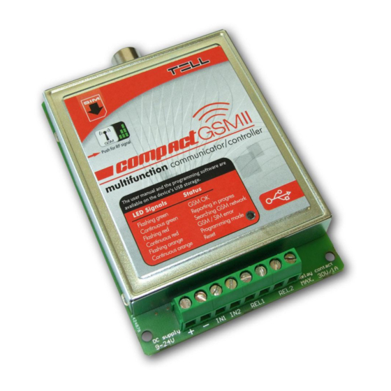
3 Module overview 4 LED signals Flashing red Searching for GSM network Continuous red GSM / SIM error Continuous green Reporting through GSM in progress Flashing green GSM network is available, idle Green performs a determined number of GSM signal query blinks after pressing the program button Flashing orange Program mode... -
Page 20: Wiring Diagram
5 Wiring diagram For normally open and normally closed setting: (REL1 and REL2 outputs are normally open) Connecting the temperature sensor:... -
Page 21: Installation Guide
6 Installation guide 6.1 Mounting Test the GSM signal strength with your mobile phone. It may happen that the signal strength is not sufficient in the desired mounting place. In this case the planned installation place can be changed before mounting the device. ...
Need help?
Do you have a question about the Compact GSM 2 and is the answer not in the manual?
Questions and answers