
Related Manuals for tell Compact-GSM


Summary of Contents for tell Compact-GSM
- Page 1 Compact-GSM INSTALLATION AND APPLICATION MANUAL for module version v1.21 and higher Rev. 1.5 16.12.2009...
-
Page 2: Table Of Contents
Table of contents 1 Module operation..........................3 1.1 Functions ..........................3 1.2 Features..........................3 1.3 Events..........................3 1.4 Functions and parameters ....................4 2 Programming..........................6 2.1 Adjustable parameters ......................6 2.2 Program menu structure ......................7 2.3 Structure of SMS containing settings ...................8 2.4 Modification of event SMS texts...................8 3 Module overview ..........................9 4 LED signals ..........................9 5 Wiring diagram ...........................10... -
Page 3: Module Operation
1 Module operation Application areas: can be used as accessory for alarm control panels or as individual GSM signaling device with 2 inputs. 1.1 Functions • GSM voice call to 4 user phone numbers on input activation with recordable message or siren tone •... -
Page 4: Functions And Parameters
1.4 Functions and parameters • Inputs The Compact-GSM module has 2 inputs (IN1 and IN2), which can be activated depending on the setting with normally open (NO) or normally closed (NC) contacts wired to COM connection point. Sensitivity of inputs is 100ms, which means event is generated only if the input is activated for at least 100ms. - Page 5 • SMS forwarding The module can forward incoming SMS messages to the first user phone number. SMS forwarding function is enabled by default, if not necessary, can be disabled in the settings menu. SMS forwarding is limited to 5 messages per day. •...
-
Page 6: Programming
• Program push-button The program push-button is placed on the panel, in the vicinity of the GSM antenna socket. Functions of the push-button are the following: - Entering programming mode: for this keep the button pressed for 3…5 seconds, then release (see „Programming” and „LED signals” chapters) - Setting time of day for test report sending: press the program button shortly three times consequently in the desired time of day. -
Page 7: Program Menu Structure
2.2 Program menu structure Key 1: User phone number settings Key 1: Enter first user phone number Key 1: Enable confirmation request Key 0: Disable confirmation request Key 2: Enter second user phone number Key 1: Enable confirmation request Key 0: Disable confirmation request Key 3: Enter third user phone number Key 1: Enable confirmation request Key 0: Disable confirmation request... -
Page 8: Structure Of Sms Containing Settings
2.3 Structure of SMS containing settings The module can send current settings in SMS (see item 6/1. of the programming menu). The settings are sent in 2 SMS messages, having the following structure: Example: CompactGSM settings (1): TEL1=06301111111/Y (TEL1…TEL4 = the 4 adjustable user phone numbers, after TEL2=06302222222/Y the phone numbers the confirmation setting can be found) TEL3=06203333333/N... -
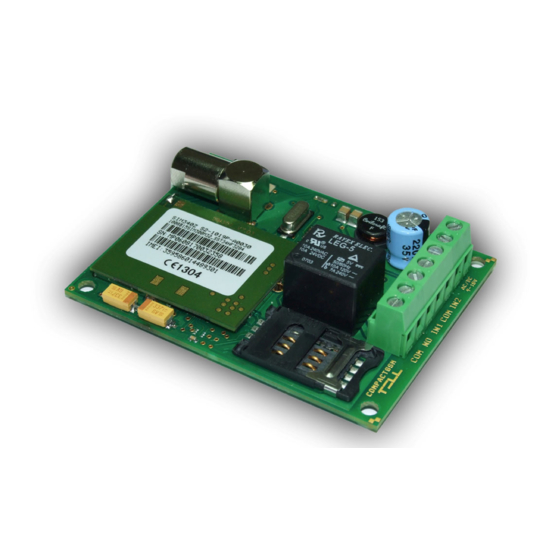
Page 9: Module Overview
3 Module overview 4 LED signals No GSM network available, or phone Red is continuously lit restart/power up in progress Red blinks fast Event transmission in progress Green blinks with longer intervals Green blinks impulsely, GSM network is available, Red is not lit standby status Green performs a determined number of GSM signal strength query... -
Page 10: Wiring Diagram
5 Wiring diagram • For Normally Open setting: • For Normally Closed setting:... -
Page 11: Installation Guide
• Check the SIM card to be placed into its case properly. • Check the antenna to be fixed properly to the Compact-GSM module. • Check the wires to be connected as instructed by the wiring diagram.
Need help?
Do you have a question about the Compact-GSM and is the answer not in the manual?
Questions and answers