Advertisement
Quick Links
Installation Instructions
Installation Instructions
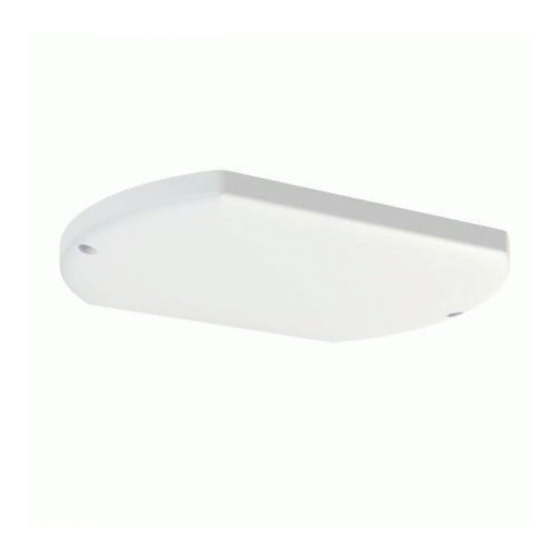
SiSo Ceiling Anetnna
CMSLP-038-4
SW3-823 - v2
1. Introduction
The CMSLP-038-4 is a UHF/3G/4G and 3.4-3.8GHz 5G ceiling mount antenna designed to be low profile and un-obtrusive. The antenna can be mounted to
non-conductive panels using the supplied nut and mounting screws. If required the antenna can also be mounted to a vertical surface such as a wall or room
divider. The antenna has low PIM chracteristics and is supplied with low PIM cable and a variety of connectors.
2. Mounting requirements and selecting location
The antenna should be mounted on non-metallic / non-conductive panels. Mounting on a metal surface will have a detrimental affect on performance.
The antenna should normally be placed in a flat, horizontal orientation with the cable exit at the top. It is also possible to mount the antenna on a wall or room
divider in a vertical orientation with the cable exit at the side. When ceiling mounted, the antenna should be mounted centrally within the desired coverage
area and when mounted vertically to a wall or divider, the antenna should be deployed facing in the desired direction of coverage.
The antenna should be spaced as far away from any nearby metal structure as possible. Ensure that there is access and adequate clearance behind the
panel and that the coaxial cable can be routed to the equipment.
Ensure that the selected mounting location can safely be accessed using the equipment that is available.
3. Antenna Mounting
Where the antenna will be fitted on a lift out ceiling panel, it may be preferable to remove it and mount the antenna on the panel whilst working at ground
level.
Mark the position for the centre fixing and make a clearance hole for the relevant connector. In the case of an N female connector this will be 18mm (3/4")
and in the case of a 4.3-10 female connector it should be 24mm (1"). Drill a pilot hole first and then increase to the required size.
If using the optional additional screw fixings mark the position of the mounting holes (the antenna can be used as a template) & drill. Plastic M6 screws are
supplied but If mounting to an appropriate material self tapping screws can be used. Screws should be M6 or 1/4 inch pan head screws of an appropriate
length for the installation. Using metal screws may negatively impact low PIM performance.
Remove the supplied nut and mount the antenna being careful not to kink or damage the cable. Refit the nut and tighten. Tighten any screw fixings, but note
that over-tightening may damage the antenna cover.
3. Routing and terminating coaxial cables(s)
The cable must be routed up or out and directly away from the antenna and should not run parallel to or lie flat on the antenna. Run the cable to the wireless
terminal, ensuring that the cable is secured and protected from subsequent damage during access. The cable should not be kinked and the minimum bend
radius of 32mm (1.25") must be observed.
If cable ties are used, they should not be overtightened, as this will distort the cable profile and could affect the antenna performance. Any excess cable
should be laid "side by side" (not coiled) and can be loosely secured by cable ties or tape.
Connectors should be cleaned with air or a soft brush and then tightened to the correct torque which is 1Nm for the N type or a maximum of 5Nm for 4.3-10
connectors.
Advertisement

Related Manuals for Panorama Antennas CMSLP-038-4


Summary of Contents for Panorama Antennas CMSLP-038-4
- Page 1 1. Introduction The CMSLP-038-4 is a UHF/3G/4G and 3.4-3.8GHz 5G ceiling mount antenna designed to be low profile and un-obtrusive. The antenna can be mounted to non-conductive panels using the supplied nut and mounting screws. If required the antenna can also be mounted to a vertical surface such as a wall or room divider.
- Page 2 4. Commission and test Check the comms cables: • Carry out VSWR check, the VSWR should measure <2.5:1 in transmit band. • Connect the cable to the radio device • Check the system PIM level if necessary 5. Mounting using central bush 5.