Advertisement
CMWB2-038-6-NJ
1. Introduction
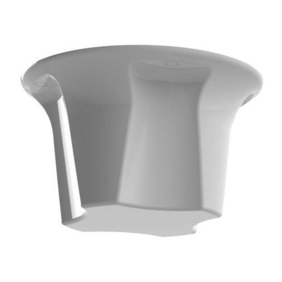
The CMWB2-038-6-NJ is an ultra-wideband low PIM ceiling mounted antenna covering
380MHz to 6Ghz. The antenna features an integrated groundplane and can be
mounted on metallic or non-metallic ceilings. The antenna can be mounted by way of
its N connector mounting bush or utilising optional additional screw fixings concealed
beneath the antenna's removable snap fit caps.
2. Select a suitable mounting location
The antenna is omni-directional and should be mounted as centrally as possible within
the desired coverage area. The roof space should be accessible at this location to
permit routing of cables to the radio.
Select a flat, level location on the desired ceiling which is free from obstructions and
not too close to other ceiling mounted items - consider downward projection of
antenna and any height clearance issues with low ceilings.
Take care to avoid mounting the antenna in close proximity to metal ceiling furniture
such as girders, joists and air conditioning units as these objects may affect the
antenna's performance.
3. Mount the antenna
If the ceiling is constructed with removable ceiling tiles, it may be best to remove the
tile, mount the antenna, and then re-fit.
Remove the thumbscrew nut from the N type connector and set aside.
If the mounting hole caps are fitted and use of those holes is required by the
installation the caps should be carefully extracted and set aside.
Mark the position of the mounting holes & RF connector and drill appropriate holes.
Alternatively if mounting to an appropriate material self tapping screws can be used.
Screws should be M6 or 1/4 inch pan head screws of an appropriate length for the
installation.
Mount the antenna base plate on the ceiling tile and replace the thumbscrew nut
tightening it firmly. Utilise M6 or 1/4 inch screws to secure the installation if required.
Replace the snap fit mounting hole caps.
4 Route and terminate the coaxial cable
Route the coaxial cable from the radio or combiner to the mounting location, taking
care to avoid running it adjacent to existing wiring or ceiling furniture. Next fit a
suitable male N-type coaxial connector or adaptor (as applicable) to the cable and
connect the cable to the antenna. For a low PIM installation suitable low PIM cables
and connectors should be used. When connecting the N male connector to the N
female bulkhead located on the antenna the recommended torque is 100 Ncm.
5 Commission and test
Using a suitable antenna analyser, carry out a VSWR test in each freq. band. A VSWR of
<3:1 should be achieved at 380-400MHz UHF and a VSWR of < 2:1 should be achieved
across all other bands.
SW3-654 - V1 - Panorama Antennas Ltd
Advertisement
Table of Contents

Subscribe to Our Youtube Channel
Related Manuals for Panorama Antennas CMWB2-038-6-NJ


Summary of Contents for Panorama Antennas CMWB2-038-6-NJ
- Page 1 CMWB2-038-6-NJ 1. Introduction The CMWB2-038-6-NJ is an ultra-wideband low PIM ceiling mounted antenna covering 380MHz to 6Ghz. The antenna features an integrated groundplane and can be mounted on metallic or non-metallic ceilings. The antenna can be mounted by way of its N connector mounting bush or utilising optional additional screw fixings concealed beneath the antenna’s removable snap fit caps.
- Page 2 Fig.3 Mount antenna through selected Fig.4 Replace thumbscrew and tighten to surface. secure the installation. Fig.5 Secure the installation with screws (if Fig.6 Check over and test installation. required) and replace snap fit caps. SW3-654- V1 - Panorama Antennas Ltd...
Need help?
Do you have a question about the CMWB2-038-6-NJ and is the answer not in the manual?
Questions and answers