Table of Contents
Advertisement
Quick Links
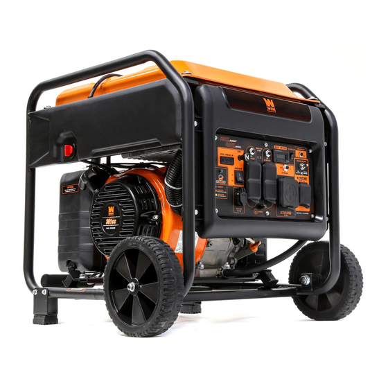
MODEL GN625iX
6250-WATT
INVERTER GENERATOR
Instruction Manual
NEED HELP? CONTACT US!
Have product questions? Need technical support? Please feel free to contact us:
1-800-232-1195 (M-F 8AM-5PM CST)
TECHSUPPORT@WENPRODUCTS.COM
IMPORTANT: Your new tool has been engineered and manufactured to WEN's highest standards for dependability,
ease of operation, and operator safety. When properly cared for, this product will supply you years of rugged,
trouble-free performance. Pay close attention to the rules for safe operation, warnings, and cautions. If you use
your tool properly and for its intended purpose, you will enjoy years of safe, reliable service.
WENPRODUCTS.COM
For replacement parts and the most up-to-date instruction manuals, visit
Advertisement
Table of Contents

Related Manuals for Wen GN625iX


Summary of Contents for Wen GN625iX
- Page 1 1-800-232-1195 (M-F 8AM-5PM CST) TECHSUPPORT@WENPRODUCTS.COM IMPORTANT: Your new tool has been engineered and manufactured to WEN’s highest standards for dependability, ease of operation, and operator safety. When properly cared for, this product will supply you years of rugged, trouble-free performance. Pay close attention to the rules for safe operation, warnings, and cautions. If you use your tool properly and for its intended purpose, you will enjoy years of safe, reliable service.
-
Page 2: Table Of Contents
CONTENTS WELCOME Specifications ....................3 Introduction ..................... 4 SAFETY General Safety Rules ..................5 Generator Safety Warnings ................7 BEFORE OPERATING Unpacking & Packing List ................9 Know Your Generator ..................10 Assembly & Adjustments ................12 Generator Preparation ..................14 OPERATION &... -
Page 3: Welcome
SPECIFICATIONS GENERATOR Model Number GN625iX Surge (Starting) Wattage 6250W Rated (Running) Wattage 5000W Rated Voltage 120V / 240V AC Rated Amperage 41.6A / 20.8A Phase Single Frequency 60 Hz Product Weight With Wheel Kit 119.5 lbs Product Weight Without Wheel Kit 109.6 lbs... -
Page 4: Introduction
INTRODUCTION Thanks for purchasing the WEN 6250-Watt Inverter Generator. Refer to the illustration below for the location of the serial number on the specifications label. Record the generator information in the spaces provided below. If assis- tance for information or service is required, please contact customer service by calling 1-800-232-1195, M-F 8-5 CST;... -
Page 5: Safety
GENERAL SAFETY RULES WARNING! Read all safety warnings and all instructions. Failure to follow the warnings and instructions may result in electric shock, fire and/or serious injury. Safety is a combination of common sense, staying alert and knowing how your item works. The term “power tool” in the warnings refers to your mains-operated (corded) power tool or battery-operated (cordless) power tool. - Page 6 GENERAL SAFETY RULES WARNING! Read all safety warnings and all instructions. Failure to follow the warnings and instructions may result in electric shock, fire and/or serious injury. Safety is a combination of common sense, staying alert and knowing how your item works. The term “power tool” in the warnings refers to your mains-operated (corded) power tool or battery-operated (cordless) power tool.
-
Page 7: Generator Safety Warnings
GENERATOR SAFETY WARNINGS DANGER! CARBON MONOXIDE Using a generator indoors CAN KILL YOU IN MINUTES. Generator exhaust contains carbon monoxide (CO). This is a poison gas you cannot see or smell. If you can smell the generator exhaust, you are breathing CO. But even if you cannot smell the exhaust, you could be breathing CO. - Page 8 GENERATOR SAFETY WARNINGS WARNING! Do not let comfort or familiarity with the product replace strict adherence to product safety rules. Failure to follow the safety instructions may result in serious personal injury. OPERATING ENVIRONMENT 3. If any part of the generator, electrical device or pow- er cord is broken, damaged, or defective, make sure 1.
-
Page 9: Before Operating
GENERATOR SAFETY WARNINGS WARNING! Do not let comfort or familiarity with the product replace strict adherence to product safety rules. Failure to follow the safety instructions may result in serious personal injury. TO MAXIMIZE THE LIFESPAN OF YOUR GENERATOR: We recommend running your generator at least once a month for 20 to 30 minutes. -
Page 10: Know Your Generator
KNOW YOUR GENERATOR TOOL PURPOSE Generators provide you with power when and where you need it most. Refer to the following diagrams to become familiarized with all the parts and controls of your Generator. The components will be referred to later in the manual for assembly and operation instructions. - Page 11 KNOW YOUR GENERATOR CONTROL PANEL 1. Indicator Lights 8. Voltage Selector Switch The output light (green) will turn on when the recep- Switch between 120V and 240V outlets. tacles have power, the overload light (red) will turn 9. NEMA L14-30R on if the generator is overloaded, the oil light (yellow) AC 120V/240V split-phase.
-
Page 12: Assembly & Adjustments
ASSEMBLY & ADJUSTMENTS HIGH ALTITUDE OPERATION ABOVE 3000 FEET WARNING! To prevent serious injury from The fuel system on this generator may be affected by opera- fire, follow the kit installation procedures in a tion at high altitudes. Proper operation can be ensured by well-ventilated area away from ignition sources. - Page 13 ASSEMBLY & ADJUSTMENTS WARNING! Do not turn on the generator until it is fully assembled according to the instructions. Read through and become familiarized with the following procedures of handling and adjusting your tool. Failure to follow the safety instructions may result in serious personal injury. •...
-
Page 14: Generator Preparation
GENERATOR PREPARATION The following section describes the necessary steps to prepare the generator for use. If you are unsure about how to perform any of the steps please call 1-800-232-1195 (M-F 8-5 CST) for customer service. Failure to perform these steps properly can damage the generator or shorten its life. - Page 15 GENERATOR PREPARATION TO CHECK OIL LEVEL (before every subsequent start): Fig. 5 1. Place the generator on a level surface. Make sure the engine is OFF before adding or checking oil. 2. Remove and wipe the dipstick with a clean rag. Upper Limit 3.
- Page 16 GENERATOR PREPARATION TO ADD GASOLINE: Fig. 6 Fuel Cap 1. Place the generator on a level surface. Make sure the engine is OFF before adding or checking the fuel. 2. Unscrew the fuel cap (Fig. 6) and set it aside. The fuel cap may be tight and hard to unscrew.
-
Page 17: Operation & Maintenance
STARTING THE GENERATOR Before starting the generator, make sure you have read and performed the steps in the “Generator Preparation” sec- tion of this manual. If you are unsure about how to perform any of the steps in this manual please call 1-800-232-1195 (M-F 8-5 CST) for customer service. - Page 18 STARTING THE GENERATOR BEFORE STARTING THE GENERATOR 1. Verify that the generator is outside on a dry, level surface. Allow at least two feet of clearance on all sides of the generator. 2. To maximize safety, check that the generator is properly grounded. Refer to "Step 3 - Ground The Generator." 3.
-
Page 19: Using The Generator
USING YOUR GENERATOR CALCULATING THE WATTAGE OF YOUR DEVICE(S) Connect electrical devices running on AC current according to their wattage requirements. Calculate the total run- ning wattage and starting wattage of the device(s) you wish to connect, and MAKE SURE that they are within the capacity of your generator and the capacity of each individual outlet. - Page 20 USING YOUR GENERATOR CALCULATING THE WATTAGE OF YOUR DEVICE(S) - CONTINUED The chart below serves as a reference for the estimated wattage requirements of common electrical devices. How- ever, do not solely rely on this chart - all electronics and appliances are built differently. Always check the wattage listed on the electrical device before consulting this chart.
- Page 21 USING YOUR GENERATOR CONNECTING ELECTRICAL DEVICES 1. Before connecting electrical devices, allow the generator to run for a few minutes to stabilize the speed and volt- age output. Turn the voltage selector switch to 120V or 240V, depending on the appliance(s) connected. NOTE: You cannot use the 120V and 240V outlets at the same time.
- Page 22 USING YOUR GENERATOR LIGHT MEANING RESOLUTION GREEN (POWER INDICATOR) (OVERLOAD) Generator output is normal. No action needed. Flashes 1x, repeating Voltage at alternator is too low. No elec- Check for loose connections. Call every 3 sec trical output. 1-800-232-1195 for assistance. Flashes 2x, repeating Engine speed is too low.
- Page 23 • The CO sensor has a lifetime of about 7 years, and is capable of monitoring its lifetime. If your generator shows an error light several years after purchase, it may be time to replace the CO sensor. Contact WEN customer service...
-
Page 24: Shutting Off The Generator
SHUTTING OFF THE GENERATOR CAUTION! Unplugging running devices can cause damage to the generator. Never stop the engine with elec- trical devices connected and running. WARNING! Allow the generator to cool down before touching areas that become hot during use. CAUTION! Allowing gasoline to sit in the fuel tank for long periods of time can make it difficult to start the gen- erator in the future. -
Page 25: Maintenance
MAINTENANCE RECOMMENDED MAINTENANCE SCHEDULE Proper routine maintenance of the generator will help prolong the life of the machine. Please perform maintenance checks and operations according to the maintenance schedule below, Table 4. If there are any questions about the maintenance procedures listed in this manual, please contact customer service at 1-800-232-1195 (M-F 8-5 CST), or email techsupport@wenproducts.com. - Page 26 MAINTENANCE CLEANING YOUR GENERATOR Keep the generator clean to prevent improper operation or machine damage from dirt and debris. Inspect all ventila- tion openings on the generator. These openings must be kept clean and unobstructed. If the generator becomes dirty, use a damp cloth to wipe exterior surfaces. Use a soft bristle brush to loosen dirt and oil and use a vacuum to pick up loose dirt.
- Page 27 MAINTENANCE DRAINING THE CARBURETOR Fig. 13 Drain the carburetor after every use and before storing the generator (refer to Table 4). Draining the carburetor can help prevent build-up and blockages caused by stagnant fuel inside of the carburetor. 1. Prepare an approved gasoline-storage container under the carburetor to collect the drained fuel.
- Page 28 MAINTENANCE INSPECTING/CLEANING THE SPARK ARRESTOR Fig. 15 Inspect and clean the spark arrestor every 100 hours of operation (refer to Table 4). The spark arrestor is located outside the muffler, which gets very hot during operation. Allow the engine to cool completely before servicing the spark arrestor.
- Page 29 MAINTENANCE 5. Measure the plug gap with a spark plug gap gauge. The Fig. 16 gap should be 0.7 to 0.8 mm (0.028-0.031 in). Carefully adjust the gap if necessary. See Fig. 16. 0.7 - 0.8mm 6. Screw the spark plug back into the spark plug hole us- ing the spark plug wrench.
-
Page 30: Transportation & Storage
TIP: Your WEN generator is compatible We highly recommend running your generator once a month for with the WEN 56409 Generator Cover (not 20 to 30 minutes. Plug in a small load in to ensure there is proper included). It is available for purchase at power output. -
Page 31: Troubleshooting Guide
8. CO levels too high. 8. Refer to "CO Sensor Information" on p. 23. 9. Connect or install the CO sensor. If an error 9. CO sensor disconnected, is shown, contact WEN customer service for removed, or faulty. assistance. 10. Ghost in the generator. - Page 32 TROUBLESHOOTING GUIDE WARNING! Stop using the generator immediately if any of the following problems occur or risk serious personal injury. If you have any questions, please contact customer service at 1-800-232-1195 (M-F 8-5 CST), or email techsupport@wenproducts.com. PROBLEM POSSIBLE CAUSE SOLUTION 1.
-
Page 33: Wiring Diagram
WIRING DIAGRAM... -
Page 34: Exploded View & Parts List
EXPLODED VIEW & PARTS LIST NOTE: Replacement parts can be purchased from wenproducts.com, or by calling our customer service at 1-(800) 232-1195, M-F 8-5 CST. Parts and accessories that wear down over the course of normal use are not covered by the two-year warranty. Not all parts may be available for purchase. ASSEMBLY 1 - CYLINDER HEAD, ASSEMBLY 2 - CRANKCASE SPARK PLUG... - Page 35 EXPLODED VIEW & PARTS LIST ASSEMBLY 3 - CRANKCASE COVER ASSEMBLY 4 - CRANKSHAFT Part No. Description Qty. Part No. Description Qty. GN625i-0401 Crankshaft Assembly GN625i-0301 Crankcase Cover GN625i-0302 Crankcase Cover Gasket ASSEMBLY 5 - PISTON RING SET, GN400i-0205 CONNECTING ROD Oil Dipstick GN625i-0304 Subassembly...
- Page 36 EXPLODED VIEW & PARTS LIST ASSEMBLY 6 - VALVE TRAIN, CAMSHAFT ASSEMBLY 7 - RECOIL STARTER Part No. Description Qty. Part No. Description Qty. GN625i-0701 Bolt, M6x20 GN625i-0601 Camshaft Assembly Recoil Starter GN400i-0602 Valve Lock Nut GN625i-0702 Assembly GN400i-0603 Valve Adjustment Nut GN625i-0703 Flat Washer, 6mm GN625i-0604...
- Page 37 EXPLODED VIEW & PARTS LIST ASSEMBLY 8 - SHROUD, LOWER SHIELD ASSEMBLY 9 - CARBURETOR Part No. Description Qty. Part No. Description Qty. GN625i-0901 Air Filter Gasket 56200-1202 Bolt, M6x12 GN625i-0902 Carburetor Assembly GN625i-0802 Retaining Ring GN625i-0903 Carburetor Gasket GN625i-0803 Shroud Carburetor Insulator GN625i-0904...
- Page 38 Muffler Bracket 11-7 56310i-1103 Screw, M6x60 12-8 GN400i-1104 Bolt, M8x16 11-8 GN625iX-1108 Rotor 11-9 GN625iX-1109 Stator 11-10 GN625i-1110 Flat Washer, 6mm NOTE: Not all parts may be available for purchase. Parts and accessories that wear down over the course of...
- Page 39 EXPLODED VIEW & PARTS LIST ASSEMBLY 13 - FUEL TANK Part No. Description Qty. Part No. Description Qty. 13-1 GN625i-1301 Fuel Tank 13-10 GN625i-1310 Fuel Tank Chain Clip 13-2 56380i-1207 Fuel Tank Damper 13-11 GN400i-1205 Breather Valve 13-3 GN625i-1303 Bushing 13-12 GN625i-1312 Breather Hose 13-4...
- Page 40 EXPLODED VIEW & PARTS LIST ASSEMBLY 14 - FRAME Part No. Description Qty. Part No. Description Qty. 14-1 GN625iX-1401 Frame Assembly 14-13 56200-0706 Bolt, M6x10 14-2 GN625i-1402 Nut, M10-1.25 14-14 GN400i-1311 Bolt, M6x8 14-3 56310i-1404 Nut, M8 14-15 GN625i-1415 Cllp...
- Page 41 CO Sensor LED Indicator 15-26 GN625iX-1526 Bracket 15-14 GN400i-1413 Grounding Nut 15-27 GN625iX-1527 CO Sensor LED Indicator 15-15 GN625i-1515 USB Outlet Assembly CO Sensor Engine 15-28 GN625iX-1528 Control Module NOTE: Not all parts may be available for purchase. Parts and accessories that wear down over the course of...
- Page 42 EXPLODED VIEW & PARTS LIST ASSEMBLY 16 - WHEEL AND HANDLE Part No. Description Qty. Handle Tube 16-1 GN625i-1601 Assembly 16-2 GN625i-1602 Handle Sleeve 16-3 GN625i-1603 R-clip 16-4 GN625i-1604 Bolt, M6x30 16-5 GN625i-1605 Handle Bracket 16-6 GN625i-1606 Handle Pin 16-7 GN625i-1607 Handle Damper 16-8...
-
Page 43: Warranty Statement
Contact techsupport@wenproducts.com or 1-800-232-1195 with the following information to make arrangements: your shipping address, phone number, serial number, required part numbers, and proof of purchase. Damaged or defective parts and products may need to be sent to WEN before the replacements can be shipped out. - Page 44 THANKS FOR REMEMBERING V. 2021.05.14...
Need help?
Do you have a question about the GN625iX and is the answer not in the manual?
Questions and answers