Table of Contents
Advertisement
HOFFRICHTER GmbH
Mettenheimer Straße 12 / 14
19061 Schwerin
Germany
Telephone:
+49 385 39925 - 0
Fax:
+49 385 39925 - 25
E-mail:
info@hoffrichter.de
www.hoffrichter.de
LAVI Patient ENG_2019-09-25_5.0
5
0
0
0
0
6
8
2
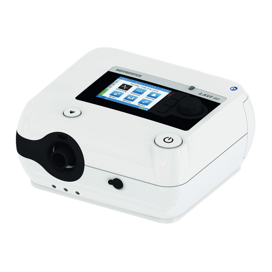
LAVI
Ventilator
User's manual
for patients
Applies to device types 9LV401 and 9VL402 from device software 1.400
Advertisement
Table of Contents

Related Manuals for Hoffrichter LAVI


Summary of Contents for Hoffrichter LAVI
- Page 1 Mettenheimer Straße 12 / 14 19061 Schwerin Ventilator Germany Telephone: +49 385 39925 - 0 Fax: +49 385 39925 - 25 E-mail: info@hoffrichter.de www.hoffrichter.de User's manual for patients Applies to device types 9LV401 and 9VL402 from device software 1.400 LAVI Patient ENG_2019-09-25_5.0...
- Page 3 ©2019 HOFFRICHTER GmbH All rights reserved. The content published in this user’s manual is the sole property of HOFFRICHTER GmbH. All forms of reproduction, editing, distribution and use of any kind, even in part, require the prior written consent of HOFFRICHTER GmbH.
- Page 4 Every HOFFRICHTER GmbH device is supplied with a serial number for traceability pur- poses. Please enter your device’s serial number here. You will find the serial number on the rating plate on the bottom of the device..........Please always provide the serial number in case of queries and complaints.
-
Page 5: Table Of Contents
Table of contents Chapter 1 ..................9 Introduction ......................9 Scope of delivery ....................10 Symbols ......................11 Intended purpose ....................15 User qualification ....................17 Chapter 2 ..................19 Safety Information ....................19 General safety instructions ................... 20 Electrical safety ....................22 Installation requirements and transport .............. - Page 6 Chapter 5 ..................51 Operating the Device ..................51 Menu structure ....................53 Menu lock ......................54 User profiles ......................55 Home screen ....................... 56 Monitoring screen ....................58 Parameter screen ....................59 Event log screen ....................61 System screen ..................... 62 Statistics screen ....................
- Page 7 Manufacturer’s declaration on electromagnetic compatibility........ 92 Disposal ......................96 Disclaimer ......................97 Inhaltsverzeichnis...
- Page 8 List of figures Figure 1: Rating plate ................12 Figure 2: Front side of device ..............28 Figure 3: Rear of device ................28 Figure 4: Left device side ................28 Figure 5: Bottom of device ............... 29 Figure 6: Top of device ................
-
Page 9: Chapter 1
Chapter 1 Introduction Please note: This user’s manual for patients is included in the scope of delivery. It does not replace the user’s manual for physicians and medical professionals. Chapter 1: Introduction... -
Page 10: Scope Of Delivery
Return to Home screen Unlocking key on/off key Disconnect Aqua- • Start ventilation: press briefly TREND uni from LAVI • Stop ventilation: press briefly + MFK • Switch device on: Press ≥ 4 s • Switch device off: Press ≥ 4 s 19.8 1:1.5... -
Page 11: Symbols
Symbols Symbols on the packaging Symbol Meaning European Article Number Article number Serial number CE mark and number from the notified body. The medical device complies with the applicable regulations of EU 93/42/EEC for medical products. Transport and store package with arrows pointing up at all times. Fragile contents Protect from moisture! Humidity range during storage and transport... -
Page 12: Figure 1: Rating Plate
Symbols on the rating plate The rating plate is on the bottom of the device. LAVI 40 Ventilator Type: 9LV402 SN: CEA1700011 Made in Germany -INPUT Li-Ion RRC2054 DC-INPUT max. 15l/min 15V / 3.2Ah / 48Wh max. 3.75A 500 hPa HOFFRICHTER GmbH Mettenheimer Str. - Page 13 Symbols on the device Symbol Meaning Housing Follow the instructions in the user’s manual. Connections sensor connection DC connection COM interface Connection of remote alarm/nurse call (ESD-sensitive component – do not touch!) USB interface Oxygen connection Control Release button for the integrable humidifier On/off button Chapter 1: Introduction...
- Page 14 Symbols used in this user’s manual Important information is denoted by symbols in this user’s manual. Please ensure that you follow these instructions in order to prevent accidents, personal injury and mate- rial damage. In addition, the local accident prevention regulations and general safety regulations in force in the area of use must be observed.
-
Page 15: Intended Purpose
If the prescribed ventilation is no longer possible due to a techni- cal error, an acoustic alarm is emitted for at least 2 minutes. If LAVI is operated with an internal battery, ventilation can continue on without dis- ruption in the event of a power failure. - Page 16 Indication LAVI can be used for the following indications: • Obstructive ventilation disorders (e.g. COPD) • Restrictive ventilation disorders (e.g. scoliosis, thorax deformities) • Neurological, muscular and neuromuscular disorders (e.g. paralysis of the diaphragm) • Central breathing regulation disorders Regardless of the indications named here, use of the device always depends on the doctor’s individual diagnosis.
-
Page 17: User Qualification
Side effects The following undesired side effects may occur in connection with artificial respiration: Invasive ventilation: • Complications due to tube / tracheal cannula • Gastric inflation Mask ventilation: • Pressure points and skin defects in the face • Eye irritation due to leaks •... - Page 18 Chapter 1: Introduction...
-
Page 19: Chapter 2
Chapter 2 Safety Information Please note: Heed all important information in this user’s manual. Otherwise, there is a risk of accidents, injury and material damage. Chapter 2: Safety warnings... -
Page 20: General Safety Instructions
• The device must only be used on patients whose clinical record indicate it. • LAVI is not intended for use in vehicles, planes or helicopters. • Please take the care to ensure that the patient remains connected to the tubing circuit during ventilation. - Page 21 • In order to ensure patient safety, the device must be operated in such a way that all adjustable alarms are activated and adjusted to the patient. • Alarms must not be ignored. They indicate conditions that require an immediate action.
-
Page 22: Electrical Safety
• Only the supplied power supply unit may be used for operating the ventilator. • Only LAVI and a humidifier may be connected to a power strip. Additional power strips or extension cables must not be plugged in to this power strip. -
Page 23: Installation Requirements And Transport
• To disconnect the device from the mains supply, unplug it. • Before cleaning the device, the plug must be disconnected from the electrical outlet. • Do not reach for the device under any circumstances if it falls into water. Installation requirements and transport Risk of injury due to the device falling down! Ö... -
Page 24: Instructions Before Commissioning
• Observe the user’s manual of the manufacturer or distributor from whom you obtain your oxygen. • If the patient is supplied with oxygen via the device, the FiO should be measured. • On the LAVI, FiO measurement is possible using the optional FiO sensor. We recommend using this particular sensor exclusively. -
Page 25: Safety-Related Test
• In the event of an oxygen leak, the oxygen supply should be shut off immediately. The room must be ventilated immediately. Any sparks, fire or potential fire sources in the vicinity of the device must be avoided. • Oxygen supports combustion. Therefore, observe the fire protection regulations applicable for using oxygen. - Page 26 Chapter 2: Safety warnings...
-
Page 27: Chapter 3
Chapter 3 Description of Device Chapter 3: Description of device... -
Page 28: Front Side Of Device
Front side of device Connection leakage tube circuit/ humidifier Connection FiO sensor cable Contact socket for integrable humid- ifier AquaTREND uni Figure 2: Front side of device Rear of device Oxygen connection DC connection The DC plug is connected here. See also page 35. -
Page 29: Bottom Of Device
Bottom of device SD card slot An SD card here can be inserted here. Rating plate Battery compartment cover The internal battery is located under LAVI 40 Ventilator Type: 9LV402 Made in Germany SN: CEA1700011 -INPUT Li-Ion RRC2054 DC-INPUT max. 15l/min 15V / 3.2Ah / 48Wh... - Page 30 Explanation and functions of the softkeys Symbol Meaning Alarm key Function Condition Action Confirmation of all current Active alarms Press briefly alarms Confirm no longer active alarms Saved alarms Press briefly Mute the audible alarm for 2 Press briefly min (audio alarm pause) Cancel the audible alarm Audio alarm paused Press briefly...
- Page 31 Symbol Meaning Clinic mode active Home mode active Alarm active Red: high priority Yellow: middle priority Turquoise: low priority Alarm inactive Grey: inactive, regardless of the continuation of the alarm condition Audio alarm paused The audible alarm has been paused for 2 min. The audible alarm of a new alarm event will also be paused for 2 min.
- Page 32 Symbol Meaning Menu lock active The home and escape keys are deactivated and the MFK functions are restricted. It is not possible to access the menu. Internal battery charging Power level of the internal battery 100% green: about 60% ... 100% red: about 20% ...
-
Page 33: Chapter 4
Chapter 4 Commissioning Chapter 3: Description of device... -
Page 34: General Information
• Never operate the device without the air filter. • Only use original HOFFRICHTER filters. • If the device was previously in an environment where the air temperature was not the same as in the new operating location, allow approximately 1 hour until the temperatures have evened out before commissioning. -
Page 35: Power Supply
Power supply The ventilator can be supplied by two different power sources: • Mains connection via power supply unit • Internal battery The ventilator automatically detects which power sources are available. If the device is connected to a power supply unit, the power supply unit is used as the primary source and the internal battery as the secondary source. -
Page 36: Figure 9: Mains Connection Via Power Supply Unit
5. Insert the mains cable plug into the power socket (100 - 240 V, 50/60 Hz). 6. Press the on/off button for more than 4 s to switch on the LAVI. 7. The device boots while performing a self-test: •... -
Page 37: Figure 10: Start Screen
The booting progress is displayed by a progress bar (A). The status (B) is also displayed: • Booting... → Device is booting • Error message → Error detected, press MFK to continue. All error messages are listed on page86. The device cannot be started if certain errors are in effect. - Page 38 Standby operation If device mains operation is switched on and respiration is switched off, the device can be placed into standby operation. This means that the device automatically moves into a sleep mode after the last operation. A standby screen will be displayed. If the device has an internal battery, this will be charged and the power level will be shown.
- Page 39 Operation with internal battery Battery operation means that the device is supplied with power by the internal battery. If the device is supplied with power by the internal battery, the device automatically switches off after two minutes if ventilation is not active. Please note: •...
- Page 40 The device will automatically switch off the ventilation 5 minutes after the “Internal battery empty” alarm occurs. A notice window will appear “Ventilation currently not possible. Internal battery empty”. The device will switch off once another minute has passed. This prevents the battery from being fully drained and ensures the device shuts down properly.
-
Page 41: System Setup, Non-Invasive Ventilation
System setup, non-invasive ventilation Risk of injury due to tube circuit and cable! If laid incorrectly, the tube circuit or other cables (e.g. pulse oximetry) could cause patient strangulation. Ö Tubes and cables must always be positioned so that they cannot wrap around the neck or limbs of the patient. -
Page 42: System Setup, Invasive Ventilation
System setup, invasive ventilation Risk of injury due to tube circuit and cable! If laid incorrectly, the tube circuit or other cables could cause patient strangulation. Ö Tubes and cables must always be positioned so that they cannot wrap around the neck or limbs of the patient. Risk of suffocation due to missing exhalation valve! If no option for exhaling through a separate valve is available in the invasive ventilation system, the patient could suffocate. -
Page 43: Figure 13: System Setup, Invasive Ventilation With External Humidifier
Setup with external humidifier Please note: • Use an approved humidifier according to DIN EN ISO 8185 with a humidity out- put of > 33 mg/l. • Follow the manufacturer user’s manual. • The humidifier should be positioned below the patient and the device, so that no water can accumulate in the patient’s lungs or in the ventilator. -
Page 44: Figure 14: System Setup, Invasive Ventilation With Hme Filter
Setup with HME filter If no humidifier is used, we recommend using an HME filter to maintain the moisture of the respiratory gas. A “combined filter” consisting of an HME filter and a bacterial filter is well-suited (e.g. Medisize Hygrovent HMEF). Please note: When using a HME filter, read the user’s manual from the respective manufacturer. -
Page 45: Calibrating The Tube Circuit
Calibrating the tube circuit A tube calibration function is available in the device to enable use of different tube cir- cuits and accessories. During tube calibration, the resistance of the circuit upstream of the air outlet is determined, which forms the basis for correct pressure measurement. Perform tube calibration when changes have been made to the system upstream of the air outlet. - Page 46 If the calibration was not successful, “Error” - - . - - : - . - - . - - - will appear. Calibrate Tube Error In the event of an error, check the entire sys- 100 l/min tem. Resistance in the overall system may be too high.
-
Page 47: Figure 15: Inserting The Sd Card
To be able to pass on therapy data to a doctor, you can copy the data to an SD card. You can use SD and SDHC cards up to 32 GB. You can format the SD card on LAVI and delete any existing data. -
Page 48: Figure 16: Removing Sd Card
4. Once successfully copied, the message “Fin- - - . - - : - . - - . - - - ished...ok” will appear. Copy Data Press the MFK to close the notice window. Finished...ok Press the MFK to Continue Set 1 5. -
Page 49: Using The Functional Bag
If important device functions are not shown or available, proper operation cannot be guaranteed. Ö Only use the original HOFFRICHTER functional bag. The functional bag protects the ventilator in mobile use (e.g. at the wheelchair or walker) from mechanical damage or effects of the weather. The functional bag is avail- able as an accessory (see page 89). -
Page 50: Switching On The Device
If you are using oxygen therapy during ventilation, please note the safety infor- mation for using oxygen from page 24. Mains operation Connect the device to the mains supply. To switch the LAVI on, press the on/off but- ton for more than 4 seconds. Battery operation To switch the LAVI on in battery operation, press the on/off button for more than 4 seconds. -
Page 51: Chapter 5
Chapter 5 Operating the Device Chapter 5: Device operation... -
Page 52: Menu Structure
Menu structure Start screen Booting... SW-Version x.xxx 19.8 1:1.5 0.570 Thursday I 19.05.2016 I 23:10 Home screen Monitoring Parameter Event Log System Statistics Service Set 1 Monitoring Parameter Eventlog screen screen screen 19.8 1:1.5 0.570 19.8 1:1.5 0.570 19,8 1:1,5 0,570 Measurements Graphs... - Page 53 System Statistics Service screen screen screen - - , - - : - , - - , - - - 19,8 1:1,5 0,570 - - . - - : - . - - . - - - Calibrate Tube Set 1 Set 2 Set 3 Enter PIN...
-
Page 54: Menu Lock
Menu lock The menu lock function can be used to The following keys retain their full func- protect against the accidental changing tionality: of device settings. It locks the following • Alarm key operating elements: • Heating key • Home key •... -
Page 55: User Profiles
To deactivate the menu lock: 1. Hold the MFK for more than 1 second 19,8 1:1,5 0,570 until the window appears at the side. Disable Menu Lock Keep the MFK pressed until the prog- ress bar has completed and is dis- To disable the menu lock keep pressing the MFK. -
Page 56: Home Screen
Home screen You can enable individual screens from the home screen: • Monitoring screen – Measurements: Monitoring measurements (numerical) – Graphs: Monitoring measurements (graphs) • Parameter screen • Selecting the ventilation set, setting the ventilation and alarm parameters • Event log screen –... - Page 57 To enable a screen: 1. Navigate to the desired screen by turning 19.8 1:1.5 0.570 the MFK. Thursday I 19.05.2016 I 23:10 Selected screen symbol → black Monitoring Parameter Event Log Symbol not selected System Statistics Service → blue Set 1 2.
-
Page 58: Monitoring Screen
Monitoring screen The ventilation parameters are shown in real time on the monitoring screen. The monitoring screen is divided into 2 sections: • Measurements • Graphs Measurements Depending on the configuration, the following parameters are shown under “Mon- itoring” > “Measurements” when ventilation is active: •... -
Page 59: Parameter Screen
Parameter screen The ventilation and alarm parameters are 19.8 1:1.5 0.570 shown on the parameter screen. The phy- Set 1 Set 2 Set 3 sician can create up to 3 sets with differ- Time Inspiration 2.0 s I-Slope ent ventilation modes and parameters. E-Slope Sigh Function High Inspiration Volume... - Page 60 4. Change the setting to “Yes” and 19.8 1:1.5 0.570 press the MFK to confirm the set- Set 1 Set 2 Set 3 Activate Set ting. Mode IPAP 20.0 hPa PEEP 5.0 hPa Frequency 12 bpm Time Inspiration 2.0 s I-Slope Set 1 Chapter 5: Device operation...
-
Page 61: Event Log Screen
Event log screen The event log screen is divided into three areas: • Events • Alarms • Alarms Alarms Physiologically-dependant alarms whose 19,8 1:1,5 0,570 alarm limits have been set in the param- Alarms Alarms Events eter screen are stored under “Alarms ”. 15.07.2016, 23:41 l Set 1 Apnoea The only technically-dependent alarms... -
Page 62: System Screen
System screen On the system screen, you can set the - - , - - : - , - - , - - - basic device settings, perform calibrations Calibrate Tube and view device information. Calibrate FiO Sensor Copy Data Format SD-Card Load User Settings Save User Settings... - Page 63 Change the device language To change the device language setting: 1. On the home screen, navigate to “System” and press the MFK. 2. Navigate to the 14th menu item with the MFK. - - , - - : - , - - , - - - Screen Change Standby...
-
Page 64: Statistics Screen
Statistics screen The evaluation of the ventilation param- 19,8 1:1,5 0,570 eters is performed for each ventilation Set 1 Set 2 Set 3 set based on percentiles. Percentiles are Minute Ventilation MV [l] 8,000 the dispersion measurement of the sta- 6,000 tistical data distribution during ventila- 4,000... -
Page 65: Chapter 6
The LAVI ventilator is equipped with fixed and adjustable alarms, relating to the respec- tive ventilation modes. There are three alarm priorities:... - Page 66 Alarm test The user does not have to perform any alarm tests. However, the following describes an option to call the “Disconnection” alarm in order to perform a manual check of the alarm system. To check the “Disconnection” alarm: 1. Connect the device to the mains supply. 2.
-
Page 67: Audible Alarm Output (Audio Alarms)
Audible alarm output (audio alarms) Audio alarms are issued in a sequence of beeps. Alarm tones differ depending on alarm cause and priority. You will find more information from page 69. If the alarm sound equipment is defective and emits no sound, the audible alarms will be triggered by a second alarm sound transmitter which emits only a simple audible alarm. -
Page 68: Visible Alarm Output
Visible alarm output Visible alarms are displayed as follows: • via the info LED • on the toolbar • as a textbox Alarm output via the info LED The info LED may take on 3 different statuses, to signify the current alarm priority. •... -
Page 69: Alarm Overview
Alarm overview Adjustable alarms The adjustable alarms are physiologically conditional alarms. Only the doctor can set the alarm limits on the parameter screen. Please note: Not all alarms can be paused. Alarm Priority Audible Info LED Cause Time delay alarm status Apnoea HIGH... - Page 70 Alarm Priority Audible Info LED Cause Time delay alarm status Low vol- MEDIUM c a f Yellow Tidal volume is 3 breaths in a flashing lower than the “Min. tidal vol- ume” High min- MEDIUM c a f Yellow Minute ventilation 3 breaths in a ...
- Page 71 Priority Audible Info LED Cause Correction alarm status No sys- HIGH C c c – C c No leak in the Use an exhalation tem flow flashing ventilation sys- valve for the ven- tilation mask. Check the air out- let with a CPAP mask.
- Page 72 Priority Audible Info LED Cause Correction alarm status Mini- HIGH c a f – a f Measured min- mum vol- flashing imum volume ume not less than set reached “Minimum Vol- ume” Internal HIGH c c c – c c Communica- Switch device on ...
- Page 73 Priority Audible Info LED Cause Correction alarm status 1 This alarm is only possible if at least one of the alarms “Max. FiO ” or “Min. FiO ” is activated. 2 Nominal battery value = Muting = Inactive (can be disabled) = Can be deleted by pressing the MFK Fixed inactive alarms The “Internal battery error”...
-
Page 74: Messages
Messages Message output on the toolbar Messages are shown on the toolbar. If an error occurs, the alarm is shown in place of the message, as the alarm has a higher priority. Back-up Frequency Active Set 1 A Message Figure 28: Messages on the toolbar Message overview Message... -
Page 75: Chapter 7
Chapter 7 Cleaning and Exchange of Components Chapter 6: Alarms and messages... -
Page 76: Important Information
• Do not immerse the device in water or solvents. • Follow the accessory manufacturer’s instructions for cleaning and disinfection. Overview The following overview table describes the cleaning intervals of articles delivered by HOFFRICHTER. For articles by other manufacturers, please follow their cleaning instruc- tions. Component Name... - Page 77 Component Name Cleaning Replace Oxygen connection as needed adapter Carrying case as needed Filter cassette as needed (without filter) Coarse filter weekly Cleaning Fine filter monthly, if severely contaminated sensor as needed in accordance with manufacturer instructions Bacterial filter daily Functional bag as needed 1 For cleaning information, please read the section...
-
Page 78: Cleaning The Device
Cleaning the device Domestic use For cleaning the surface of the device, use a cloth moistened with soapy water. Then wipe with a cloth moistened with clear water in order to remove any remaining of the soapy water. The device must be completely dry before commissioning. Cleaning the mask Risk of injury due to damaged mask! A heavily worn or damaged mask can result in insufficient... -
Page 79: Cleaning The Exhalation Valve
Cleaning the exhalation valve For reasons of hygiene, clean the exhalation valve once a week. To do so, proceed as follows: 1. Clean the exhalation valve with mild soapy water. Do not use any other agents! 2. Rinse the exhalation valve thoroughly with clear water. 3. - Page 80 Cleaning the coarse filter Clean the black course filter weekly. 1. Remove the filter cassette from the device (see Figure 29). 2. Remove the coarse filter (black) from the filter cassette. 3. Clean the filter with mild soapy water. Do not use any other agents! 4.
-
Page 81: Chapter 8
Chapter 8 Routine Tests and Maintenance Work Chapter 8: Routine checks and maintenance work... -
Page 82: Overview
Please note: You must not perform any testing or maintenance work. Maintenance work may only be performed by an authorised service company. The device has an expected service life of min. 5 years provided the maintenance work listed in the following overview is performed by an authorised service company and the device is used according to the user’s manual. -
Page 83: Battery Maintenance
Battery maintenance The LAVI internal battery is a powerful lithium-ion battery. To reach the full capacity of the battery, it is important to charge it on a regular basis. If the “Battery maintenance” message appears, you should charge the battery to 100%, discharge it and then charge it to 100% again to recalibrate the battery indicator. - Page 84 Chapter 8: Routine checks and maintenance work...
-
Page 85: Chapter 9
Chapter 9 Annex Chapter 9: Appendix... -
Page 86: Error Messages
Error messages The following error messages may arise while booting the device: Error message Cause Solution Flash not working No access to the flash Device cannot be booted and must be serviced Default parameters are No valid parameter set avail- The device uses the default on the device able or faulty... -
Page 87: Figure 30: Error List
After booting, any errors in effect will be displayed on the toolbar via the error symbol. To show the error list detailing existing errors, press the error key on the home screen. - - , - - : - , - - , - - - Error Primary alarmsound not working... -
Page 88: Technical Data
Specifications and performance characteristics Dimensions (W x D x H) 215 x 203 x 115 mm Weight 2.2 kg Max. inspiratory working pressure LAVI 30: 30 hPa LAVI 40: 40 hPa Min. inspiratory working pressure 4 hPa Supply voltage Operating conditions Temperature range + 5°C to + 40°C... -
Page 89: Accessories
Accessories Please note: Make sure to follow all general safety guidelines when using accesso- ries from page 20. To order accessories, please contact a HOFFRICHTER service partner. Name Figure Article number Mask Size XS Size S Size M Size L... - Page 90 Name Figure Article number Passive exhalation valve 00014157 Bacterial filter 00004932 connection adapter angled 41000087 measurement set consisting of: sensor, T adapter, FiO sensor adapter, FiO sensor connect- ing line with screw connector 00004944 sensor 23000018 T adapter 23000019 sensor adapter 23000020 sensor connecting line with screw connector 00014116...
- Page 91 Name Figure Article number Remote alarm box, complete including accessories 00014122 Remote alarm box without accessories 00004834 Cable for remote alarm box 00014115 LAVI functional bag 00013082 Chapter 9: Appendix...
- Page 92 Manufacturer’s declaration on electromagnetic compatibility LAVI complies with standard DIN EN 60601-1-2:2016-05 and is intended for use in the electromagnetic environment described in the following. Any deviating ambient conditions can affect its main performance characteristics (e.g. pressure accuracy or alarms) or cause the device to fail.
- Page 93 Guidance and manufacturer’s declaration - electromagnetic immunity The LAVI ventilator is intended for operation in environments as described below. The user LAVI of the ventilator must ensure it is operated in such an environment. Immunity tests IEC 60601 test level Compliance level...
- Page 94 IEC 61000-4-6 spaced at least at the in ISM suggested safety dis- Effective value and amateur radio LAVI tance to the ven- bands between 150 tilator, including wires, kHz and 80 Mhz which is calculated using the equation for trans- mission frequency.
- Page 95 5 periods pital environments. If the IEC 61000-4-11 LAVI user of the venti- > 30 % dip of U > 30 % dip of U lator requires continued 25 (50 Hz) periods/...
- Page 96 Disposal Proper disposal saves natural resources and prevents harmful substances being released into the environment. Device The device must not be disposed of with the household waste. Please con- tact the relevant customer services department to find out how to dispose of the device etc.
- Page 97 Disclaimer HOFFRICHTER GmbH accepts no liability for consequences in terms of safety, reliability and performance of the product if: • interventions, modifications, extensions, calibration, repairs and maintenance are carried out by persons not authorised by us, • other manufacturers’ accessories and spare parts are used that have not been approved by us for use on the product, •...
- Page 98 Chapter 9: Appendix...
- Page 99 Chapter 9: Appendix...
- Page 100 Chapter 9: Appendix...
- Page 101 Chapter 9: Appendix...
- Page 102 Chapter 9: Appendix...
Need help?
Do you have a question about the LAVI and is the answer not in the manual?
Questions and answers