
Related Manuals for Hoffrichter TRENDvent


Summary of Contents for Hoffrichter TRENDvent
- Page 1 Quality makes the Difference User’s manual for patients Ventilator as of device software 1.500...
- Page 2 SERIAL NUMBER Every HOFFRICHTER GmbH device is supplied with a serial number for traceability purposes. Please enter your device’s serial number here. You will fi nd the serial num- ber on the rating plate on the bottom of the device.
-
Page 3: Table Of Contents
CONTENTS Scope of delivery ................7 General ....................8 Information on user’s manual .............8 Symbols on the rating plate ...............8 Symbols used in this user’s manual ...........9 Safety information ................10 General safety instructions .............. 10 Electrical safety ................13 Installation requirements and transport ..........14 Instructions before commissioning .......... - Page 4 Commissioning ................38 Setting up the device ..............38 Using the functional bag ..............39 Power supply .................. 40 Mains operation ................40 Operation with internal battery ............41 Power failure ................41 Operation with external battery ............. 42 Setting the tube system ..............43 Connecting the valve tube system ...........
- Page 5 The curve screen ................61 “Freezing” the curve screen ............62 Scaling the time axis ..............62 Changing the measured value ............62 The ventilation sets ................. 63 Activating the ventilation set ............64 The comfort screen ................. 65 Changing the date ............... 66 Changing the time ................
- Page 6 Cleaning and disinfection ..............84 Cleaning the device ................. 84 Cleaning the coarse fi lter ..............85 Cleaning the mask ................86 Cleaning the tube system ..............86 Valve tube system ................ 86 Leakage tube system ..............87 Cleaning the oxygen sensor ............87 Cleaning the humidifi...
-
Page 7: Scope Of Delivery
SCOPE OF DELIVERY User’s manual and CLICKpad Microfi bre cloth Functional bag brief instructions TRENDvent ventilator Adapter for oxygen connection, straight Mains cable Spare fi lter Power supply cassette Leakage tube system with pressure measuring tube and 2 plugs Spare Spare fi... -
Page 8: General
GENERAL INFORMATION ON USER’S MANUAL Read this user’s manual through carefully before using the ventilator for the fi rst time. Follow the safety and cleaning instructions in particular. Keep the manual in a safe place close to the device so that you can refer to it immediately if necessary. -
Page 9: Symbols Used In This User's Manual
SYMBOLS USED IN THIS USER’S MANUAL Important information is denoted by symbols in this user’s manual. Be sure to follow these instructions in order to avoid accidents, personal injury and material damage. In addition, the local accident prevention regulations and general safety regulations in force in the area of use must be observed. -
Page 10: Safety Information
SAFETY INFORMATION GENERAL SAFETY INSTRUCTIONS • Only qualifi ed, trained, specialist medical staff under the supervision of a physician may make adjust- ments to the ventilator. The device must only be used by persons who have fully read and understood this user’s manual before commissioning and have familiarized themselves with the device. - Page 11 • We recommend the use of the tube systems tested and approved for use by the manufacturer. Using other tube systems may lead to differing results. • When a valve tube system and a nasal or full-face mask is used for non-invasive ventilation, this mask must not contain an expiration opening.
- Page 12 • Filters and other parts that are connected to the device must be regularly replaced. Dispose of the replaced parts according to the regulations for used medical material and/or the local environmental protection rules. • A device that is not functioning properly may endanger the patient or operator.
-
Page 13: Electrical Safety
• Do not reach for the device under any circumstances should it fall into water. • Do not try to open the device. Maintenance and repairs may only be performed by personnel autho- rized by HOFFRICHTER GmbH. Safety information... -
Page 14: Installation Requirements And Transport
INSTALLATION REQUIREMENTS AND TRANSPORT • For operation, the device must be placed on a safe, level base. The air inlet at the rear of the device, as well as all ventilation slots, must not be blocked. • The display and all operating and display elements must not be covered and must be visible at all times. -
Page 15: Instructions Before Commissioning
INSTRUCTIONS BEFORE COMMISSIONING • A functional test must be carried out each time before commissioning (see page 89). • At temperatures below - 5 °C and over + 50 °C, the function of the device may be impaired. • Do not use the device if the housing or the cable of the device or the power supply are damaged. -
Page 16: Using Oxygen
• The FiO can be measured using the oxygen sensor optionally available from HOFFRICHTER. We recom- mend the exclusive use of these sensors (see “Accessories” on page 93.) • The oxygen sensor contains a caustic liquid. Avoid skin or eye contact if there is a sensor leak! •... -
Page 17: Safety-Related Test
• When supplying oxygen, it should be ensured that only dry gas (O ) is used. Increased residual moisture may lead to device defects. If necessary, a humidifi er can be connected between the air outlet of the device and the patient. •... -
Page 18: Intended Use
INTENDED USE The use of the device contrary to its intended use can lead to a haz- ard to the health of the patient. The device is used for pressure-controlled respiratory support, as well as the ventilation of patients who are not completely dependent on mechani- cal ventilation. -
Page 19: Contraindications
CONTRAINDICATIONS Respiratory therapy may be contraindicated for certain pre-existing conditions. The following conditions may be a contraindication for non-invasive ven- tilation: • Severe cardiac arrhythmia • Severe hypotension • Severe epistaxis • Pneumothorax or pneumomediastinum • Pneumoencephalus • Cranial trauma •... -
Page 20: Side Effects
SIDE EFFECTS The following undesired side effects may occur in connection with artifi - cial respiration: Invasive ventilation: • Complications due to tube / tracheal cannula Mask ventilation: • Pressure points and skin defects in the face • Eye irritation due to leaks •... -
Page 21: How The Device Works
HOW THE DEVICE WORKS IMPORTANT COMPONENTS The TRENDvent ventilator comprises the following components: • Blower • DC / Communication • Sensors / valves (compressed air distribution) • Power supply • Controller (control and operating unit) • Interfaces Switching Remote alarm... - Page 22 Blower The blower provides a maximum pressure of 40 hPa at a fl ow of 200 l/min. On the air inlet side there is an air fi lter cassette with a coarse and a fi ne fi lter. Power supply The device is supplied with power via an AC/DC switching power supply or the internal battery.
- Page 23 Distribution of air in the device For the distribution of the compressed air, the device is composed of the following units: • Blower (40 hPa at 200 l/min ) • Air outlet (standardized tube connector [M22]) with fl ow element and proportional valve •...
- Page 24 Interfaces The device has an USB interface for connection to a PC. This interface enables the PC software VENTcontrol to be used to communicate with the device and software updates can be carried out. There is also a con- nection for the nurse call or a remote alarm box. For servicing, the device has an RS232 interface.
-
Page 25: How The Device Works
HOW THE DEVICE WORKS The function of the TRENDvent ventilator is based on a control mecha- nism, which adjusts the power of the blower to the air output required for therapy in a closed loop. The blower power is controlled by the signal of the respiratory pressure and the signal of the inspiration fl... -
Page 26: Nurse Call And Remote Alarm
Alarms The alarm conditions are continuously checked. In the event of an alarm, an alarm tone sounds and the corresponding message appears on the display. The alarm button also lights up depending on the priority of the alarm. If the alarm conditions are no longer present, the alarm sound is switched off. -
Page 27: Ventilation Modes
VENTILATION MODES Depending on the tube system used, the following ventilation modes can be set in the device. Valve tube system Mode Description Pressure Controlled Ventilation APCV Assisted Pressure Controlled Ventilation Pressure Supported Ventilation PSV-S Pressure Supported Ventilation - Spontaneous Table 1: Valve tube system CPAP Continuous Positive Airway Pressure... -
Page 28: Pcv Mode
PCV MODE In the PCV mode, the ventilation is controlled exclusively through the device. The patient is unable to breathe spontaneously. For controlled ventilation, the inspiration trigger must be set to “OFF”. The respiratory cycle is based on the set frequency and a set I:E ratio. The inspiration pressure (IPAP) and end expiration pressure (PEEP) defi... -
Page 29: Apcv Mode
APCV MODE The adjustable ventilation parameters in pressure controlled assisted ven- tilation, correspond to those in purely controlled ventilation. By setting an inspiration trigger, the patient has the option to interrupt expiration and trigger the next inspiration, by making an effort to breathe and reach the trigger threshold. -
Page 30: Psv Mode
PSV MODE Pressure supported ventilation is intended to support spontaneous breath- ing and to initiate machine ventilation whenever spontaneous respiration fails. The support pressure (IPAP) and expiration pressure (PEEP) defi ne the pressure range in which the patient is ventilated. The trigger thresh- olds of the inspiration trigger and the expiration trigger can be adjusted to the patient’s requirements. -
Page 31: Psv-S Mode
PSV-S MODE The PSV-S mode corresponds to the adjustable ventilation parameters of the PSV mode. As the frequency is set to “OFF”, the trigger is only released when the patient breathes spontaneously. The apnea time automatically becomes an alarm parameter. In this setting, the device only reacts to the patient’s spontaneous respiration CPAP MODE... -
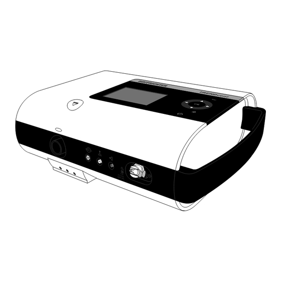
Page 32: Description Of Device
DESCRIPTION OF DEVICE HOUSING, DISPLAY AND CONTROL ELEMENTS Display Operating unit Unlocking button for humidifi er Connection for tube system/ humidifi er Handle Contact sockets for humidifi er Oxygen sensor cable connection (jack = 2.5 mm) Oxygen Control tube connection connection (... - Page 33 Tube system switch Sign for power supply Main switch Mains socket 24V~/5A Service connection (RS232 interface, Remote alarm LED Air inlet with integrated RJ11) fi lter cassette (fi ne and coarse fi lter), detachable PC connection Remote alarm (USB interface) connection (RJ10) Connection cover...
-
Page 34: Operating Unit
OPERATING UNIT OPERATING UNIT ELEMENTS Power LED Battery LED esc button Touch wheel Cursor buttons OK button Alarm button Heating button ON/OFF button Fig. 9: Operating unit elements Description of device... -
Page 35: Led Functions
LED FUNCTIONS Power LED The power LED provides information about the power supply. Color Condition Power supply green Voltage > 22.0 V Voltage < 22.0 V fl ashing none Voltage > 22.0 V (confi rmed) Table 3: Power LED Battery LED The battery LED provides information about the capacity of the internal battery. -
Page 36: Button Functions
BUTTON FUNCTIONS esc button Essentially, the esc button has the following functions: • Cancel calibrations, parameter changes or similar. The set values are not applied. The old values are retained. • Cancel marking a parameter. • Switching the display to the superordinate screen, up to the patient screen. - Page 37 Heating button The heating button switches the humidifi er heating on and off. The heating button also provides information about the status of the heating. Holding down the heating button (> 3 s) also enables you to go directly to setting the heating level.
-
Page 38: Commissioning
• Never operate the device without the air fi lter. • Only use original HOFFRICHTER fi lters. If the device was previously in an environment where the air temperature was very different from the operating location, you should wait approximately 1/2 an hour before commissioning until the temperatures have evened out. -
Page 39: Using The Functional Bag
The device must not be operated in bags other than the HOFFRICH- TER functional bag. The functional bag is optionally available from HOFFRICHTER as an accessory. In order to ensure the operating safety, the following instructions must be adhered to. -
Page 40: Power Supply
POWER SUPPLY The ventilator can be supplied with power from 3 different sources: • Power supply from power socket • Internal battery • External battery pack (optional accessory) The ventilator automatically detects which power sources are available. If the device is connected to an external voltage source via the power sup- ply unit, this is always used fi... -
Page 41: Operation With Internal Battery
OPERATION WITH INTERNAL BATTERY To prevent the internal battery from discharging, the device should stay connected to the mains power during standby times. Charging a completely empty battery takes approximately 4 hours. If the device is switched on without a connection to the mains power, or the device is disconnected from the mains power during operation, an alarm sounds and the message “Battery Operation”... -
Page 42: Operation With External Battery
LED lights green. At full capacity and factory settings, the AKKUPACK uni BASE enables TRENDvent to operate for up to 10 hours. Using AKKUPACK uni BASE together with AKKUPACK uni PLUS doubles operation time to up to 20 hours. -
Page 43: Setting The Tube System
SETTING THE TUBE SYSTEM The device is suitable for use with a valve tube system, as well as for use with a leakage tube system. Before using the device for the fi rst time, or if switching to a different tube system, the type of tube system to be used must be set on the device. -
Page 44: Connecting The Valve Tube System
CONNECTING THE VALVE TUBE SYSTEM The valve tube system consists of: Ventilation tube Expiration valve Patient connection Air outlet Device connection Valve control tube for the expiration valve Pressure measuring tube Connect the valve tube system as follows: 1. Ensure that the device has been set up for the use of a valve tube system (see page 43). -
Page 45: Connecting The Leckage Tube System
CONNECTING THE LECKAGE TUBE SYSTEM Connect the leakage system as follows: 1. Ensure that the device has been set up for the use of a leakage tube system (see page 43). 2. Attach the leakage tube system with the device-connection side to the device’s tube connection. -
Page 46: Connecting The Humidifier
CONNECTING THE HUMIDIFIER The AquaTREND uni humidifi er must not be used for invasive ventilation. The AquaTREND uni humidifi er can be used to humidify the respiratory air. 1. Connect the humidifi er to the device as in Fig. 18 until it locks into place. -
Page 47: Connecting The Bacterial Filter
CONNECTING THE BACTERIAL FILTER To protect the device from infection during patient changes, we recom- mend the permanent use of suitable bacterial fi lters (e.g. MEDISIZE BARR- VENT S). Connect the bacterial fi lter as follows: 1. Attach the bacterial fi lter to the device’s tube connection. 2. -
Page 48: Switching The Device On
SWITCHING THE DEVICE ON An sound must be emitted when the device is switched on. If this is not the case, the device must not be used and should be checked by an authorized service technician. The tube system may already be connected when the device is started, but not yet connected to the patient. -
Page 49: Switching The Device Off
SWITCHING THE DEVICE OFF 1. Stop ventilation by pressing the ON/OFF button. A signal sounds and the display shows the query: 2. Press the cursor to select “Yes”, followed by the OK button. Sub- sequently, a signal sounds 3 times and the ventilation stops. 3. -
Page 50: Starting Ventilation
STARTING VENTILATION The expiration valve must be open during ventilation. Ensure that the opening is not covered, as the expiration air can otherwise not escape and thereby hinder ventilation. Switch the ventilator on. Press the ON/OFF button. Ventilation starts. The ON/OFF button lights up green and the pressure bar can be seen in the patient screen. -
Page 51: Operation With Humidifier
OPERATION WITH HUMIDIFIER Connect the AquaTREND uni humidifi er as described on page 46. The humidifi er features an integrated heating system for heating the humidifi er water. This enables the respiratory air to be preheated. During battery operation (see page 41), the humidifi er’s heating is deac- tivated and the heating button fl... -
Page 52: Switching On The Heating
SWITCHING ON THE HEATING To switch on the humidifi er’s heating, press the heating button (function description see page 37). The color of the heating button changes from white to green. If the heating is in standby mode (heating button fl ashing green) and you start ventilation, the heating is automatically started. -
Page 53: Using Oxygen
USING OXYGEN Before using oxygen, the safety instructions as of page 16 must be read. The supply of oxygen is possible in all ventilation modes. Please note that changes to the ventilation parameters, such as e.g. respiratory pressure, I:E, respiratory frequency, will lead to a change in FiO content. -
Page 54: Measuring Oxygen Concentration
MEASURING OXYGEN CONCENTRATION Oxygen can only be measured in combination with a valve tube system with an expiration valve. Use the optionally available oxygen sensor for this. Depending on the ambient conditions, the sensor can require up to 30 min- utes after installation to reach signal stability. - Page 55 Oxygen sensors have a limited durability. A durability of 15 months after the date of manufacture applies for oxygen sensors supplied by HOFFRICHTER. The service life of the sensors is 6 months. After that, the oxygen sensor must be replaced by a new one. The date of manufacture can be found on the oxygen sensor.
-
Page 56: Operating The Device
OPERATING THE DEVICE OPERATING CONCEPT The device is operated via the controls on the operating unit. The principal operating structure is represented in the fol- lowing fi gure. As soon as your hand comes near to the operating unit, the control elements and the display light up. Patient screen Curve screen or on alarm... -
Page 57: Changing Screens
CHANGING SCREENS Press the cursors to switch to the previous or next screen. If the patient screen is active, pressing the cursors displays the last screen selected. SAFETY LOCK To protect against accidental or unauthorized alteration of the ventilation and alarm parameters, the device features a safety lock. Apart from switch- ing to the curve and patient screens, no actions can be carried out if the safety lock is activated. -
Page 58: The Patient Screen
THE PATIENT SCREEN During normal operation the patient screen is shown on the display. The patient screen provides information about the active ventilation set, as well as the ventilation running time in hours. If several ventilation sets are recorded, a different ventilation set can be activated in the patient screen. During ventilation the pressure bar provides constant information about the pressure profi... -
Page 59: Symbol Area
SYMBOL AREA Symbol Meaning The symbol indicates the remaining capacity of the internal battery. The battery is charged during mains operation. The constantly fi lling battery display indi- cates that the battery is charging. The device is set for operation with a valve tube sys- tem (see page 43). -
Page 60: Changing The Ventilation Set
Symbol Meaning The symbol indicates that the mask test is active. Once the set mask test time has expired, the symbol vanishes. The symbol indicates that the softstart ramp is active. Once the set softstart time has expired, the symbol van- ishes. -
Page 61: The Curve Screen
THE CURVE SCREEN The curve screen provides a graphical display of the pressure, volume and fl ow in the form of a curve chart. To activate the curve screen from the patient screen, press the OK button. To leave the curve screen and return to the patient screen, press the esc button. -
Page 62: Freezing" The Curve Screen
Immediately after the activation of the curve screen during ventilation, the curves are set up over the set period of time. The curves are then replaced with the new values. The current ventilation status is shown via a white progress bar. If a new calculation of the curve starts at the beginning of the time axis, this symbol is briefl... -
Page 63: The Ventilation Sets
THE VENTILATION SETS A ventilation set contains all ventilation parameters relevant to ventilation. A maximum of 3 ventilation sets can be preconfi gured by the physician. Depending on this you have 1 to 3 ventilation sets. Display of the active set Indication that by pressing the Active cursor further screens can be... -
Page 64: Activating The Ventilation Set
ACTIVATING THE VENTILATION SET To ventilate the patient with a ventilation set’s settings, the respective ven- tilation set must be activated. To do this, proceed as follows: 1. Activate the desired ventilation set using the cursors 2. Select “ Activate Set” using the cursor or touch wheel. -
Page 65: The Comfort Screen
THE COMFORT SCREEN The comfort screen contains the following basic device settings: • Date and time • Volume of alarms • Brightness and contrast of the display In addition, the following comfort functions can be set: • Heating Level • Automatic Start •... -
Page 66: Changing The Date
CHANGING THE DATE 1. Activate the comfort screen using the cursors 2. Select “Date” using the cursor or the touch wheel. 3. Press the OK button. 4. Set the year using the cursors or the touch wheel. 5. Press the OK button. 6. -
Page 67: Setting The Automatic Start
SETTING THE AUTOMATIC START The automatic start enables ventilation to be started through the patient’s own efforts to breathe. If the mask slips, falls off or uncompensatable leaks occur, ventilation continues and a signal sounds. 1. Activate the comfort screen using the cursors 2. -
Page 68: Setting The Softstart Time
SETTING THE SOFTSTART TIME The use of the “Softstart” function can bring some relief if the patient has not really become accustomed to ventilation. The softstart function slowly increases the pressure in the time programmed by you starting with a defi ned initial ramp pressure, up to the prescribed pressure. -
Page 69: Setting The Mask Test Time
SETTING THE MASK TEST TIME The mask test time is the period in which the device carries out a mask test. Here, the worn mask is tested for any leakage, at max. pressure (IPAP + Additional Pressure). If the “Softstart” function is active, the mask test is carried out before the softstart ramp begins. -
Page 70: Setting The Volume Of The Alarms
SETTING THE VOLUME OF THE ALARMS 1. Activate the comfort screen using the cursors 2. Select “Alarm Volume” using the cursor or the touch wheel. 3. Press the OK button. 4. Set the desired volume using the cursors or the touch wheel. 3 settings are possible: = quiet = medium... -
Page 71: Setting The Brightness Of The Display
SETTING THE BRIGHTNESS OF THE DISPLAY During ventilation the background light of the display is dimmed 30 sec- onds after touching a button. You can set this value as follows: 1. Activate the comfort screen using the cursors 2. Select “Brightness” using the cursor or touch wheel. -
Page 72: The Alarm Screen
THE ALARM SCREEN You can view the alarm memory in the alarm screen. For more informa- tion about the alarm memory, please refer to “Saving alarms” on page 83. Indication that by pressing the Date and time of cursor, further screens can be selected alarm displayed Indication that by pressing... -
Page 73: The Counter Screen
THE COUNTER SCREEN The counter screen contains the running times for ventilation, the device and the blower. Indication that by pressing the cursor, further screens can be displayed Indication that by pressing the cursor, further screens Active can be displayed ventilation mode Ventilation running time since last reset Total ventilation time... -
Page 74: The Service Screen
THE SERVICE SCREEN Via the service screen you can undertake the manual O sensor calibra- tion (see page 54). Indication that by pressing the cursor, further screens can be displayed Indication that by pressing the cursor, further screens Active can be displayed ventilation mode Fig. -
Page 75: The Status Screen
THE STATUS SCREEN The status screen provides information about: • the hardware status, • operating voltage, • date of last battery test, • maximum battery capacity, • the device’s serial number and • the software version. The parameters in the status screen are purely for information and can- not be changed. -
Page 76: Alarms And Error Messages
The alarm limits may only be set by qualifi ed, specialist staff, under the supervision of a physician. The TRENDvent ventilator has both fi xed alarms and adjustable alarms that apply to the respective ventilation mode. All adjustable alarms remain saved when the device is switched off and are active again when it is switched on. -
Page 77: Acoustic Alarms
ACOUSTIC ALARMS Acoustic alarms are emitted by an alarm sound. As soon as the cause of the alarm disappears, the alarm sound is switched off. The alarm continues to be indicated by the orange light of the alarm button and a text message until it is confi rmed by pressing the alarm button. SUPPRESSING ALARM SOUNDS The alarm sound can be supressed by pressing the alarm button for 2 min- utes. -
Page 78: Adjustable Alarms
ADJUSTABLE ALARMS The parameters for the alarms shown in Table 10 will be adjusted by the physician. Alarm parameter/ Priority Cause Time delay alarm message Pressure Positive pressure deviation HIGH 15 s or Difference / greater than set “Pressure 3 breaths Pressure too high Diff.”... -
Page 79: Error Messages, Fixed Alarms
ERROR MESSAGES, FIXED ALARMS HARDWARE ERRORS Hardware errors are also shown in the status screen. Error message Priority Cause Remedy Pressure Sensor MEDIUM Offset values of the Device must be serviced sensor are outside valid range Sensor defective or not connected Temperature MEDIUM... -
Page 80: Further Error Messages
FURTHER ERROR MESSAGES Error Priority Cause Remedy message Device Error General error (communi- HIGH Device must be serviced cation to operating con- troller interrupted or error detected in motor control) Check Tube HIGH Setting of switch for tube Move position of set- System system was changed ting for tube system on... - Page 81 Error Priority Cause Remedy message Error Flow Pressure constant over long HIGH Device must be serviced Sensor period (> 15 s) Measured tidal volume Stenosis HIGH Check tube system lower than 30 ml Flow constant over long period (> 15 s) Excess Pressure greater 60 hPa HIGH...
-
Page 82: Fixed Alarms For Power Supply
FIXED ALARMS FOR POWER SUPPLY Error message Priority Cause Remedy Error Backup Battery block HIGH Device must be serviced Battery voltage too low Internal Battery Battery empty HIGH Battery must be charged; 1 min- empty ute until the power supply fails completely;... -
Page 83: Saving Alarms
SAVING ALARMS All alarms are saved in the device, including date, alarm time, alarm cause, and the measured values at the time of the alarm. The memory depth is approximately 1 year. READING OUT THE ALARM MEMORY ON THE DEVICE You can view the last 200 alarm messages in the alarm screen. -
Page 84: Cleaning And Disinfection
• Never operate the device without the air fi lter. • Only use original HOFFRICHTER fi lters. CLEANING THE DEVICE For cleaning the surface of the device, use a cloth moistened with soapy water. Then, wipe with a cloth moistened with clear water, in order to remove any remains of the soapy water. -
Page 85: Cleaning The Coarse Filter
CLEANING THE COARSE FILTER The coarse fi lter must be cleaned once a week. To do this, proceed as follows: Pull the cover of the air inlet from the device, as shown in Fig. 47. Slide the fi lter cassette out from the cover of the air inlet, as shown in Fig. -
Page 86: Cleaning The Mask
CLEANING THE MASK For hygienic reasons, clean the mask every day. To do this, proceed as follows: Disconnect the mask from the tube system. Clean the mask with mild soapy water. Do not use any other agents! Rinse the mask thoroughly with clear water. Let the mask dry completely in the air. -
Page 87: Leakage Tube System
LEAKAGE TUBE SYSTEM The tube system supplied is intended for use on one patient only. For reasons of hygiene, clean the leakage tube weekly. To do this, proceed as follows: Disconnect the leakage tube from the mask and the device. Seal the pressure measuring tube on both sides using the plugs, so that no water can penetrate. -
Page 88: Preparing The Device When Changing Patient
PREPARING THE DEVICE WHEN CHANGING PATIENT Before the device is used on another patient, it must be so compre- hensively cleaned and disinfected, that it is free of human pathogens. If MRSA contamination is suspected, the device must be packaged, with the appropriate labeling, and disinfected accordingly. -
Page 89: Functional Test
FUNCTIONAL TEST Until all tests have been passed, the device must not be used and should be checked by an authorized service technician. The tube system to be used and a test lung (optional accessory) are required for the functional test. 1. -
Page 90: Checking The Status Screen For Errors
CHECKING THE STATUS SCREEN FOR ERRORS When the device is started, it carries out a self-test. If any errors are detected, the status screen is automatically displayed (see Fig. 49). Possible errors must fi rst be corrected before the device can be used. CHECKING THE DATE AND TIME Switch to the comfort screen and check the date and time. -
Page 91: Maintenance And Safety-Related Test (Srt)
MAINTENANCE AND SAFETY-RELATED TEST (SRT) All procedures performed are to be recorded. To maintain and check the device functions, the device must be subjected to an annual maintenance or safety related test, carried out by an autho- rized service technician. The maintenance intervals and all necessary tasks are described, in detail, in the service manual. -
Page 92: Disposal
DISPOSAL DEVICE The device must not be disposed of with the household waste. Please contact the relevant customer services department to fi nd out how to dis- pose of the device, etc. properly. Proper disposal saves natural resources and prevents harmful substances being released into the environment. -
Page 93: Accessories
ACCESSORIES Scope of delivery Article number Functional bag 0001 4875 0001 4206 Power supply (cable approx. 1.80 m) Mains cable (approx. 1.80 m) 3110 0023 Valve tube system for adults 22 mm (1.80 m) 0001 4967 Leakage tube system with pressure measuring tube and 0000 7116 2 plugs 22 mm (1.80 m) Filter cassette complete... - Page 94 0000 3442 Silicone NIPPV full face mask, size L 0000 3438 Silicone NIPPV full face mask, size XL 0000 3462 Silicone NIPPV-PSU full face mask, size L (autoclavable) 0000 3439 For ordering of accessories, please contact a HOFFRICHTER service partner. Accessories...
-
Page 95: Technical Data
TECHNICAL DATA Power supplies Mains operation 100 ... 240 V AC (-20 %, +10 %), 50 ... 60 Hz DC operation 24 V DC / 5 A Internal battery operation Lithium-ion battery, 28.8 V (nominal voltage); 2.25 Ah External battery operation AKKUPACK uni BASE 24 V (nominal voltage), 5,4 Ah AKKUPACK uni BASE/PLUS... - Page 96 Resistance at 30 l/min without humidifi er with humidifi er Inspiratory and expiratory resistance of the Leakage tube system: < 0,9 hPa Leakage tube system: < 1,0 hPa device at the patient connection port Valve tube system: < 1,6 hPa Valve tube system: <...
- Page 97 Sound pressure range of audible alarm signal (at 1 m distance) Lowest value > 71 dBA, setting Medium value > 75 dBA, setting Highest value > 77 dBA, setting Operating and transport conditions Operating temperature - 5 °C to + 50 °C Relative humidity 10 % to 95 % Air pressure...
-
Page 98: Manufacturer's Declaration On Electromagnetic Compatibility
MANUFACTURER’S DECLARATION ON ELECTROMAGNETIC COMPATIBILITY Guidance and manufacturer’s declaration – electromagnetic emissions The TRENDvent ventilator is intended for use in the electromagnetic environment specifi ed below. The user of the TRENDvent ventilator should assure that it is used in such an environment. - Page 99 If the user cycle input lines acc. to IEC 61000-4-11 of the TRENDvent ventilator requires continued 60 % dip in U operation during power mains interruption, it 40 % U (60 % dip...
- Page 100 fi xed RF transmitters, an electromagnetic site survey should be considered. If the mea- sured fi eld strength outside the location in which the TRENDvent ventilator is used exceeds the compliance level, the TREND- vent ventilator should be observed to verify normal operation. If abnormal performance is observed, additional measures may be necessary, such as re-orienting or relocating the TRENDvent ventilator.
- Page 101 Recommended separation distances between portable and mobile RF communication equipment and the TRENDvent ventilator The TRENDvent ventilator is intended for use in an electromagnetic environment in which radiated RF disturbances are controlled. The user of the TRENDvent ventilator can help prevent electromagnetic interference by maintaining a minimum distance between portable and mobile RF communications equipment (transmitters) and the TRENDvent ventilator as recommended below, accord- ing to the maximum output power of the communications equipment.
-
Page 102: Disclaimer
DISCLAIMER HOFFRICHTER GmbH is not liable for consequences in terms of safety, reliability and performance of the product where: • interventions, modifi cations, extensions, calibration, repairs and maintenance are carried out by persons not authorized by us, • other manufacturers’ accessories and spare parts are used that have not been approved by us for use on the product, •... - Page 103 NOTES ................................................................................................................................................................................................................................................................................................................................................................................................................................................................................................................................................................................................................................... Notes...
- Page 104 HOFFRICHTER GmbH Mettenheimer Strasse 12 / 14 19061 Schwerin Germany Phone: +49 385 39925 - 0 Fax: +49 385 39925 - 25 E-mail: info@hoffrichter.de www.hoffrichter.de TRENDvent Patient ENG_2013-02-06_09 Art. no.: 5000 0397...
Need help?
Do you have a question about the TRENDvent and is the answer not in the manual?
Questions and answers