
Related Manuals for Safe Fleet PRIME DESIGN VRR-GM31G-ST


Summary of Contents for Safe Fleet PRIME DESIGN VRR-GM31G-ST
- Page 1 PRIME DESIGN, A SAFE FLEET BRAND ▪ Address: 1689 Oakdale Avenue #102, West St Paul, Minnesota 55118 Toll Free: 1.8.PRIME.RACK ▪ Fax: 651-552-1799 ▪ Email: info@primedesign.net ▪ Website: www.primedesign.net...
-
Page 2: Contents Overview
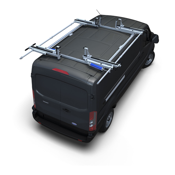
CONTENTS OVERVIEW Installer’s Note: This fully built ladder rack illustration cross-references with the STB-0001 Ship Thru Box illustration shown below, and the parts list shown on Page 3 of this Manual. STB-0001 Ship Thru Box Prime Design Limited Warranty. Seller’s sole and exclusive warranty (and Buyer’s sole and exclusive remedy and Seller’s entire liability for any breach thereof) with respect to the Goods is set forth in the Limited Warranty document available at primedesign.net/warranty-liability (the “Prime Design Limited Warranty”). - Page 3 1—L Post Assembly ..........(Qty 2) Slide, Rear, G2, Sq Cap, Bottom Mount, 9.25” 2—Z Post ..............(Qty 4) Front and Rear, Adjustable, 6.50”, Padded 3—L Post Assembly ..........(Qty 2) Front, Low Profile, Sq Cap, Top Mount, 8.50” 4—Z Post Bracket Assembly ......... (Qty 2) Front, Adjustable 5—Z Post Bracket Assembly .........
- Page 4 RECOMMENDED ASSEMBLY TOOLS (NOT INCLUDED) Installer’s Note: Do not use power tools to tighten fasteners. Power tools may lead to overtightening and cause damage to the vehicle, or the Ladder Rack hardware. Use only hand tools as shown below. Torque Wrench (inch-pound), 3/8” drive Must use for Rotation deployment Combination Wrench, 13MM Can be used for general assembly...
- Page 5 ROTATION DEPLOYMENT Installer’s Note: The Rotations on this Ship Thru rack are factory- mounted inboard of the Crossbar ends. They must be repositioned to the Crossbar’s end stops for proper operation and use. Starting with the Right Hand Rotation, use the 6 point 13MM socket, and loosen the four Barrel Nuts in positions “A”...
-
Page 6: Installation Sequence
INSTALLATION SEQUENCE SEE QUICK START GUIDE FOR ADJUSTMENTS Installer’s Note: This rack is labeled for L and Z Post installation. These will be installed with the Rotation open. Begin by removing the Ratcheting Handle from the vehicle’s cargo hold, placing it on Drive Shaft’s end, then opening the Right Hand Rotation. - Page 7 Place the Slide L Post Bracket Clamp into the inner bottom Lightly tighten the Slide L Post bolt, then finalize the alignment groove of the Slide Assembly, then position it into the L Post of the front edge of the Slide L Post as shown below in Figure C. Bracket. Assemble the Slide L Post hardware, but do not This must align to the label’s L Post positioning arrow shown in tighten until Step 1.4 the closeup in Step 1.1.
- Page 8 FRONT L POST Lightly tighten the Slide Z Post nuts, then finalize the alignment of the front edge of the Slide Z Post to the arrow as shown below in Figure F. Place the T Bolt into the notched portion of the Front Crossbar. View From Vehicle Front M8 x 25MM T Bolt Fig.
- Page 9 FRONT Z POST Repeat Steps 2.2–2.4 to complete the assembly of the Front Rotation Z Post. Place the Front Z Post Clamp onto the top of the Front Rotation Assembly, ensuring the Z Post Clamp seats into the top groove as seen in Figure G below. Repeat Step 2.3 View From Vehicle Front Fig.
- Page 10 LEFT SIDE INSTALLATION SEQUENCE Installer’s Note: Open the Left Hand Rotation to install the L and Z Posts. Repeat steps 1.1-1.4 to install the left side Rear Slide L Post. Repeat steps 2.1-2.4 to install the left side Rear Slide Z Post. Repeat steps 3.1-3.5 to install the left side Front L Post.
- Page 11 Page Intentionally Left Blank...
- Page 12 USAM-VRRGM31GSTBOX-US01 Rev-A 0518...
Need help?
Do you have a question about the PRIME DESIGN VRR-GM31G-ST and is the answer not in the manual?
Questions and answers