
Related Manuals for Valtra A800R


Summary of Contents for Valtra A800R
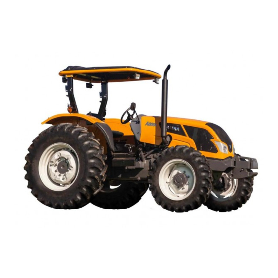
- Page 1 Workshop Service Manual A800R A850R A950R A990R Canoas October 2019 AGCO do Brasil - Av. Guilherme Schell, 10260 – Canoas/ RS ACX2831410 VALTRA is a worldwide brand of AGCO © AGCO 2019 English...
- Page 2 Find manuals at https://best-manuals.com Find manuals at https://best-manuals.com...
- Page 3 TABLE OF CONTENT Introduction Engine Clutch Gearbox Rear axle Front axle Steering system Hydraulic system Electrical system Index Find manuals at https://best-manuals.com Find manuals at https://best-manuals.com...
-
Page 4: Table Of Contents
Table of contents 1 Introduction General ..............1-3 1.1.1 Using the manual . - Page 5 Table of contents 1.6.1 Hydraulic diagram key - VT A2R ........1-51 1.6.2 Hydraulic diagram .
-
Page 6: General
1.1.1 Using the manual General The purpose of this manual is to assist Dealers and Agents in the installation, servicing and repair of Valtra equipment. It is important to follow the methods shown and to use special tools in order to perform the operations within the times stated in the repair time schedule. - Page 7 1. Introduction Description A800R A850R A950R A990R Maximum power at 80 hp 89 hp 99 hp 105 hp 2200 rpm (SAE J1995) Maximum torque at 296 Nm 330 Nm 343 Nm 348 Nm 1500 rpm Type of Free float turbocharger...
-
Page 8: Gearbox
1. Introduction Description Type Fuel injection type Common rail Cold weather start Heater grill Air filter 2-stage, dry, cartridge type with blockage indicator GUID-89CAEAD6-6FAA-4E37-B5B1-E9974733814E [V1] Cooling system Description Type Radiator Tube-shaped radiator with flat fin Additive Water + ethylene glycol-based coolant for radiators Temperature control 1 thermostat that opens between 81 °C and 85 °C Thermostat fully open at 95 °C... -
Page 9: Clutch
1. Introduction Gear transmission ratio 238.042 173.496 110.080 83.133 - - - - - - - - - - - - 68.800 50.148 21.818 24.029 175.543 127 .953 81.184 61.311 GUID-1CD83D88-2D75-4999-9FA6-008E157D7C33 [V3] 1.1.2.3 Clutch Description Type Disc Independent dual disc Transmission clutch drive Mechanical PTO clutch drive... -
Page 10: Speeds At 2000 Rpm
1. Introduction GUID-49EF52A2-46CF-48C2-82D4-F3B82D4A4040 [V5] 1.1.2.5 Speeds at 2000 rpm Standard (8F + 4R) Description/gear A800R A850R A950R A990R Front track 9.50 - 24R1 6PR 12.4 - 24R1 6PR Rear track 14.9 - 28R1 8PR 18.4 - 30R1 10PR 2.3 km/h 2.6 km/h... -
Page 11: Power Take-Off
1. Introduction Creeper (12F + 8R) Description/gear A800R A850R A950R A990R R2 (field mode - 1.0 km/h - 4.3 km/h 1.2 km/h - 4.9 km/h road mode) R3 (field mode - 1.6 km/h - 6.8 km/h 1.9 km/h - 7 .7 km/h... -
Page 12: Rear Axle Tracks
1. Introduction Description A800R A850R A950R A990R Number of shaft splines PTO 540 = 3.500 (63/18) Transmission ratio PTO 540 + 540E + 2.9524 (62/21) PTO 540 + 1000 + 2.0741 (56/27) 540 rpm / 1890 rpm 540E rpm / 1594 rpm... -
Page 13: Tyre Pressure And Load (Speed 32 Km/H)
1. Introduction Dimensions with standard track A850R A950R/A990R Description 12.4-24 R1 + 18.4-30 R1 12.4-24 R1 + 18.4-30 R1 Total width 2086 mm2086 mm 2086 mm Machine weight 3750 kg 3750 kg Min./max. front track 1528 mm/1627 mm 1528 mm/1627 mm Min./max. -
Page 14: Hydraulic Lift
1. Introduction Description Type Adjustable front axle track - tire 14.9-24 1400 mm 1519 mm 1580 mm 1699 mm 1600 mm 1719 mm 1780 mm 1899 mm Adjustable steering angle 40° Axle oscillation 13.5° Camber 1° Kingpin inclination 8° Caster 5°... -
Page 15: Hydraulics Operation
40 l/min or 57 .5 l/min Remote control resource Flow regulator (Optional) Optional 2 pieces + 1 with flow regulator. GUID-1E328CC8-4B1D-4A50-84A2-487D1C63C0C7 [V5] 1.1.2.15 Weights Description A800R A850R A950R A990R Front tires 9.50-24R1 6PR 12.4 - 24R1 6PR Rear tires 14.9-28R1 8PR 18.4 - 30R1 10PR... -
Page 16: Wheel Set
1. Introduction GUID-A24F4F34-C73F-4C94-8A91-17094FD5C28D [V3] 1.1.2.16 Wheel set Tire (STD) Front + Rear 12.4-24R1 8PR + 18.4-30R1 12PR 12.4-24R1 6PR+18.4-30R1 10PR 14.9-24R1 6PR+18.4-34R1 10PR 12.4-24R1 6PR+13.6-38R1 6PR 9.50-24R1 6PR + 14.9-28R2 6PR 12.4-24R1 6PR+18.4-30R2 6PR 12.4-24 R1 6PR+13.6-38 R1 14PR 12.4-24R1 6PR+13.6-38R1 14PRD GUID-303C53FB-E0A5-46C3-9140-348CEC971C68 [V3] 1.1.2.17 Steering system Description... -
Page 17: Tightening Torque For Wheels
1.1.2.20 Capacities and oil specifications Component Capacity Valtra oil General specification Engine 12.5 l Valtra Engine Ultra SAE 15W40 API CI-4/ ACEA E7 Fuel tank 79 l Diesel oil with maximum sulfur content of 0.5%. Biofuel with up to 7% (B7). EN 590:2009/ASTM D 975 1-D or 2-D. - Page 18 1. Introduction Surface area mm² x 0.0016 in² in² x 645.16 mm² m² x 10.7639 ft² ft² x 0.0929 m² x 2.4711 acre acre x 0.4047 Volume cm³ x 0.0610 in³ in³ x 16.387 cm³ m³ x 35.315 ft³ ft³ x 0.0283 m³...
-
Page 19: Tightening Torques
1. Introduction Pressure x 14.504 x 0.0690 Flow rate l/min x 0.2642 gal/min (US) gal/min (US) x 3.7853 l/min l/hr x 0.2642 gal/hr (US) gal/hr (US) x 3.7853 l/hr l/ha x 0.1069 gal/acre (US) gal/acre (US) x 9.3531 l/ha Speed x 0.6214 x 1.6093 Weight... - Page 20 1. Introduction Tables 2, 4 and 6 indicate the reduced tightening torque values to apply to threaded elements in assemblies with zinc-plated self-locking locknuts, phosphated or zinc-flake-coated nuts or screws, thin nuts, weldable nuts with a height of less than 0.8 d. To check these torque values, loosen the threaded element by one quarter turn and then retighten.
- Page 21 1. Introduction 15 Nm 20 Nm 40 Nm 56 Nm 57 Nm 77 Nm 26 Nm 34 Nm 72 Nm 96 Nm 100 Nm 130 Nm 68 Nm 88 Nm 160 Nm 210 Nm 240 Nm 320 Nm 130 Nm 170 Nm 340 Nm 450 Nm...
- Page 22 1. Introduction 7 .1 5/16 (44) 7/16 (43) 1280 1 1/8 1100 1360 1760 1 1/4 1200 1600 1920 2560 1 1/2 1300 2100 2700 3280 4320 5 - Tightening torque values: zinc dichromate-plated or white zinc-plated threads in inches Nominal Tensile grade Tensile grade...
-
Page 23: Tightening Torques For Hydraulic Unions
1. Introduction 1 1/8 1025 1200 1600 1 1/4 1100 1470 1800 2400 1 1/2 1180 1900 2500 3000 4000 6 - Reduced tightening torque values: phosphated or zinc-flake-coated threads in inches Nominal Tensile grade Tensile grade Tensile grade dimension SAE 1 (ISO 10.9-BS B) SAE 5 (ISO 8.8-BS S) SAE 8 (ISO 10.9-BS V) - Page 24 1. Introduction 1 - Tightening torques: hydraulic unions with 37° flare Tensile grade SAE J 514 Outside diameter Outside diameter Thread Torque of pipe, metric of pipe, in inches inch inch Min. Max. 5/16 - 24 UNF 8 Nm 9 Nm 3/16 3/8 - 24 UNF 11 Nm...
- Page 25 1. Introduction 3 - Tightening torques: hydraulic unions with metric straight thread Tensile grade ISO 6149-3 Thread Torque +10% / 0% Nominal M8 x 1 8 Nm M10 x 1 15 Nm M12 x 1.5 25 Nm M14 x 1.5 35 Nm M16 x 1.5 40 Nm...
-
Page 26: Retention Compounds And Sealing Products
1.1.5 Retention compounds and sealing products General The Loctite compounds mentioned in this manual are referred to by their industrial name. For repair purposes, use their commercial names or the corresponding Valtra references listed in the table below. Loctite product type... - Page 27 1. Introduction Loctite product type Operation Surface sealant (engine, gearbox) Threaded union sealant (prevents loosening and leakages caused by vibrations) Retainer for cylindrical assemblies (bearings, rings etc.) Strong retainer for cylindrical assemblies (bearings, rings etc.) Strong retainer for cylindrical assemblies (resistant to high temperatures) Degreasing cleaner 5206 Metallic surface sealant (gearbox housing, engine sump)
-
Page 28: Adjustments And Calibrations
1. Introduction 1.2 Adjustments and calibrations GUID-27F09651-A695-44A7-83CE-E9F816D5F15A [V2] 1.2.1 Checking and adjusting the free play of the park brake The park brake lever is adjusted according to the position of the lower handle (1) that comes from the factory with measurement (A) of 37 mm in relation to the gearbox. -
Page 29: Checking And Adjusting The Free Play Of The Clutch Pedal
1. Introduction Result The total clearance on the pedal should be around 58 mm. Part of this measurement refers to the slack between the rod (1) and the cylinder plunger (6 mm). Drive the tractor at moderate speed on flat and level ground, apply the brakes simultaneously (using the pedal lock) and verify that both rear wheels receive the same braking force and they do not have the tendency to pull to one side. -
Page 30: Checking The Tightness Of The Wheel Nuts
1. Introduction GUID-B7571207-3C3D-40A7-94B3-B232DEE32E8D [V3] 1.2.5 Checking the tightness of the wheel nuts Check the tightness of the nuts on the front and rear wheels using a torque meter. If it is necessary to tighten the nuts, do so in a cross pattern (in numerical order according to the figure) thus avoiding bulging. -
Page 31: Fuse Box
1. Introduction 1.3 Fuse box GUID-5BA4ADC6-24D7-4372-BFA7-EBF462979F3A [V1] 1.3.1 Replace a fuse GUID-93C14421-9087-4C74-B998-8B72F9504D92-high.jpg [High] Fig. 8 Position Relay Continuous flow seal relay Clutch relay Front head lamp relay K8.1 Brake lamp relay and left direction indicator K8.2 Brake lamp relay and right direction indicator Position Capacity (A) Fuse... - Page 32 1. Introduction Position Capacity (A) Fuse Brake lamp Work lamp and reverse alarm Dashboard Telemetry Continuous flow Diagnostic connector (12 V) ECU for the engine Starter motor Position Capacity (A) Fuse Starter motor Generator GUID-ED2F27DF-3BF1-4677-BB1F-F6401FB7BC28-high.jpg [High] Fig. 9 Before starting the procedure WARNING: The machine can move without warning.
- Page 33 1. Introduction Lower and lock the engine cover. 1-30 ACX2831410...
-
Page 34: Separating The Tractor
1. Introduction 1.4 Separating the tractor GUID-1E684D03-3D30-43E5-BC8B-231DA1B65F3D [V1] 1.4.1 Opening the Tractor Between the Engine and the Fuel Tank GUID-DF248C2B-FF57-4651-93A4-797185220B83-high.jpg [High] Fig. 11 NOTE: This operation to separate the engine and the fuel tank is mainly used to access the clutch assembly for removal and installation operations when replacing the engine, fuel tank, engine flywheel and crankshaft rear retaining ring. - Page 35 1. Introduction Procedure Chock the front axle beam with wooden shims (1) on both sides, to ensure the lateral balance of the front assembly to be moved. GUID-99393715-2C74-4BE7-86C5-F90BA1AEA02B-high.jpg [High] Fig. 12 Engage the park brake and chock the rear wheels with wooden wedges. GUID-153C6BC0-84BC-4F53-8D86-0E857150F093-high.jpg [High] Fig.
- Page 36 1. Introduction Remove the Cardan shaft guard (1) by loosening the bolts. GUID-E7C986B4-4075-4B17-969A-156852299A7D-high.jpg [High] Fig. 15 Make a reference mark (A) where the Cardan shaft and front wheel drive differential pinion are positioned on the flanges to ensure that they are mounted in the same position. Remove the six bolts (arrows) securing the Cardan shaft front flange to the front-wheel drive.
- Page 37 1. Introduction Place a rail (Equipment "A") under the tractor and use two trolleys (1) and (2) with height settings on the rails. Position the trolley (1) under the engine and the trolley (2) under the fuel tank (arrow), adjusting them until they touch the housing of the components.
- Page 38 1. Introduction Loosen the retaining clamp ((arrow)) for the hose connecting the suction tube to the hydraulic pump oil filter, on the filter. Disconnect the hose. GUID-9DF705B3-EED4-410B-9221-679CC9202AE4-high.jpg [High] Fig. 22 Disconnect the connector attaching the rear wiring harness to the main harness ((arrow)), next to the electrical panel.
- Page 39 1. Introduction Disconnect the electrical connectors (arrows) for the clutch pedal switch, underneath the front floor. GUID-EDB281D2-0C10-424C-9175-C3DF6F422E4D-high.jpg [High] Fig. 25 Loosen the retaining clamps ((arrow)) for the lubrication hoses of the guide bushings on the clutch thrust bearing journals. GUID-8AA53A01-8050-4779-9024-8D36436A51B9-high.jpg [High] Fig.
- Page 40 1. Introduction Loosen the connections (arrows) for the hoses of the gearbox lubricating oil cooling system, on the gearbox filter. GUID-9CD28E71-3C4B-4A8E-B52A-E06E70384364-high.jpg [High] Fig. 29 Loosen the retaining clamp (arrow) for the fuel hose and gearbox oil cooling hose. GUID-D9863F1F-BC3D-4735-9902-6BABE855004A-high.jpg [High] Fig.
- Page 41 This as a preview PDF file from best-manuals.com Download full PDF manual at best-manuals.com...
Need help?
Do you have a question about the A800R and is the answer not in the manual?
Questions and answers