Table of Contents
Advertisement
Quick Links
DISCLAIMER: No representations or warranties are made with respect to the contents of this Instruction Manual. Blue Ribbon Corp
reserves the right to revise this manual and to make changes periodically to the content thereof, without obligation
to notify any persons of such revisions.
Blue Ribbon Corp
2770 Long Road
Grand Island, NY 14072
Blue Ribbon Corporation
Instruction Manual
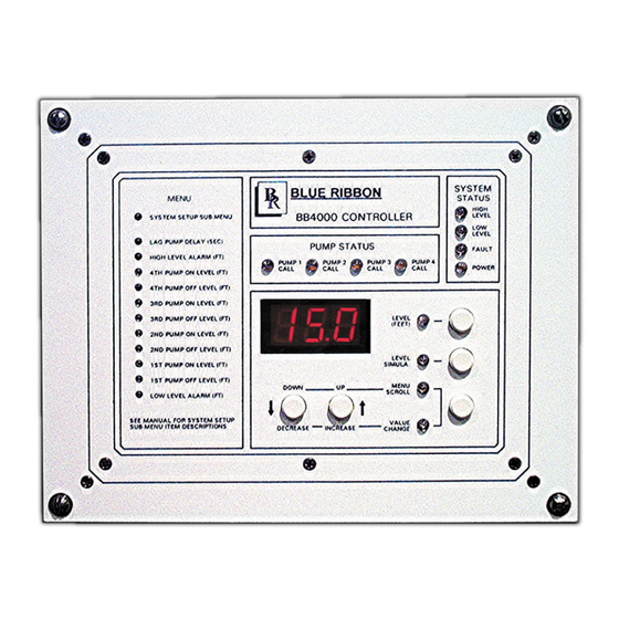
Model BB4000
Station Controller
email: brsales@blueribboncorp.com
Website: www.blueribboncorp.com
Ph: 716-773-9300
Advertisement
Table of Contents

Related Manuals for Blue Ribbon BB4000

Summary of Contents for Blue Ribbon BB4000
- Page 1 Model BB4000 Station Controller DISCLAIMER: No representations or warranties are made with respect to the contents of this Instruction Manual. Blue Ribbon Corp reserves the right to revise this manual and to make changes periodically to the content thereof, without obligation to notify any persons of such revisions.
-
Page 2: Table Of Contents
Table of Contents 1. I ....1 ntroductIon 1.1. Applications........1 1.2. - Page 3 6.2. Automatic Alternation - Parameter P .18... . 14 6.3. Forced Lead Pump Position - Parameter P .39..14 6.4. Time Based Alternation - Parameter 5.1... 14 7.
- Page 4 8.17. Float Backup - 4th On Level - Function 37..21 8.18. Float Backup - High Level - Function 38..22 8.19. Start Flush Cycle - Function 39....22 9.
- Page 5 13. f ....32 alculator 13.1. Latest Inflow Rate - The Most Recently Determined Flow Rate into the Lift Station. 32 13.2. Average Daily Inflow Total - The Flow Totals from the Last 7 days Averaged Together.
- Page 6 18.8. Forcing Pump Alternation..... . . 44 18.9. Forcing Lead Pump Position..... 44 18.10.
-
Page 7: I Ntroduction
With Analog Outputs: – External Lead Pump Selector Switch -20 °C to +50 °C (-4 °F to +122 °F) – All pump disable - for connection to Œ Level Display: 3 Digit, 7 Segment LED Phase Monitor Model BB4000 Controller Instruction Manual... -
Page 8: Ordering Information
Œ Analog Outputs: Isolated 4-20mA Maximum Load Resistance: 600Ω Œ Auxiliary Analog Inputs: Isolated 4-20mA, 250Ω Load, Transient Protected 1.5. Ordering Information Part Number: BB4000 - X X X X Number of Optional Analog Outputs: 0 = Zero Analog Outputs... -
Page 9: O Perator I Nterface F Unctions
1. Press push-button PB-M until the Menu Scroll mode indicator comes on. 2. Press push-button PB-D and PB-U as needed to arrive at the Parameter you wish to change. 3. Parameters Shown on Front of Controller: Press Push-button PB-M until the Value change indicator comes on. Model BB4000 Controller Instruction Manual... -
Page 10: How To Simulate Levels
3. Press push-button PB-M to change to the Value Change mode. 4. Press and hold for 4 seconds, either push-button PB-D or PB-U, to change the value displayed to that of the correct security code. Model BB4000 Controller Instruction Manual... - Page 11 1 = Pump Down - Empty a Tank 2 = Pump Up - Fill a Tank Note: When Parameter P.19 is Changed, New Default Level Parameter Values will be Loaded. P.20 - P.23. VFD Speed Control Setup See Page 29. Model BB4000 Controller Instruction Manual...
-
Page 12: M Enu - S Ystem S Etup
Pump 1 (2, 3, 4) Disable - Discrete Input Mode 0 = Normal 1 = Logic Inverted Fault Code See Fault Code Table on Pages 25-26. SCADA Register 40047 Note: This Automatically Returns to Zero when the Fault Clears (Except for Faults 20-29). Model BB4000 Controller Instruction Manual... - Page 13 Function assigned to the Input Function 3. See Pages 18-22 for description of each of the above Functions. Discrete Input 18 4. Pump 1 (2,3,4) Disable logic may be inverted. See Parameter P.52. F.18 Function Model BB4000 Controller Instruction Manual...
- Page 14 1 = Pump 4 Call 2 = Remote Control (SCADA Coil 30) Note: When set on “0” or “2” Pump 4 will be skipped over in all Alternation Sequence Modes. E.01 - E.62 Ethernet Port Setup See Page 37. Model BB4000 Controller Instruction Manual...
- Page 15 This feature is for alarm and telemetry only and will not function as a redundant pump off. See SCADA notes page 45. 6. Whenever the Backup Pump Control is active, the Fault indicator will be on and a fault code of 30 will be present in Parameter FLC, and set Coil 15 in SCADA Register 40001. Model BB4000 Controller Instruction Manual...
-
Page 16: M Enu - D Ata D Isplay
Flow Calculator - Pump 3 Outflow Rate F3H, F3L Gallons Per Minute See pages 32 - 35. SCADA Register 40084 F4H, F4L Gallons Per Minute Flow Calculator - Pump 4 Outflow Rate See pages 32 - 35. SCADA Register 40085 Model BB4000 Controller Instruction Manual... - Page 17 Serial Communication - Shows the Address of the Last Slave Polled by the Master See Page 47. d.09 Serial Communication - Shows the Last Modbus Function Code Received See Page 47. d.10 - d.86 Serial Communication - Shows the Entire Rest of the Modbus Message Received Model BB4000 Controller Instruction Manual...
-
Page 18: P Ump C All S Equence - Setup Parameters
Parameter P.15 may be left on its default value of 4. efault arameter etting efinitionS alue Number of Pumps Allowed to Run On Generator P.15 1 = 1 Pump 2 = 2 Pumps 3 = 3 Pumps 4 = 4 Pumps Model BB4000 Controller Instruction Manual... -
Page 19: Alternator Sequence Mode - Parameter P .16
P.17 Pump Stop Mode 1 = First On Last Off 2 = First On First Off Model BB4000 Controller Instruction Manual... -
Page 20: Automatic Alternation - Parameter P .18
Time Based Alternation Time Clock Range: 1 - 255 1/6 hour P.51 0 = Disabled 1 = 1/6 hour 6 = 1 hour 48 = 8 hours 144 = 24 hours Model BB4000 Controller Instruction Manual... -
Page 21: A Lternation S Equence M Ode
9. If connected to a SCADA system, alternation may be initiated by momentarily setting Coil 136, or by forcing the lag pump by writing to Register 40022 (Same as Parameter P.39). 10. Parameter P.51 may be used to select and setup Time Based Alterna- tion. Model BB4000 Controller Instruction Manual... -
Page 22: Pump 1 Always Lead
Coil 136, or by forcing the lead pump position by writing to Register 40022 (Same as Parameter P.39). 10. Parameter P.51 may be used to select and setup Time Based Alternation of Group #1. Model BB4000 Controller Instruction Manual... -
Page 23: Fixed Alternation
9. The External Alternation feature will not function when using this sequence. 10. The On Generator (Parameter P.15) has no effect on this sequence 11. Time Based Alternation using Parameter P.51 will not function when using this sequence. Model BB4000 Controller Instruction Manual... -
Page 24: Iscrete I Nput F Unctions
If no pumps were running when the Discrete Input is closed, the alternation of the designated lead pump will still occur. Typically this input is connected to contracts from an external Time clock. Model BB4000 Controller Instruction Manual... -
Page 25: On Generator - Function 7
When a Discrete Input programmed for “Low Level Alarm” is closed, the Low Level indicator will come on and the Low Level Alarm relay contacts will close. This Function is for alarm and indi- cation only and will not disable pump operation. Also see Function 32. Model BB4000 Controller Instruction Manual... -
Page 26: High Level Alarm - Function 18
Pump Up Mode (Parameter P.19 = 2) All available pumps will be called to run when the “Float Backup - Low Level” input closes, assuming that the “Float Backup - Off Level” input is closed. See Page 55. Model BB4000 Controller Instruction Manual... -
Page 27: Float Backup - Off Level - Function 33
8.17. Float Backup - 4th On Level - Function 37 When a Discrete Input programmed for “Float Backup - 4th On Level” closes, the Float Backup logic will issue one pump call assuming that the “Float Backup - Off Level” is closed. See Page Model BB4000 Controller Instruction Manual... -
Page 28: Float Backup - High Level - Function 38
ΠWith the Level Input Source set for the Level Probe (Parameter F.19 = 2 or 3), if not already on, the High Level Alarm will be activated when Electrode 1 is covered with liquid. Model BB4000 Controller Instruction Manual... -
Page 29: Low Level Alarm
Fault Code. The Fault Code may also be reset remotely by setting Coil 31 in SCADA Register 40002. Model BB4000 Controller Instruction Manual... -
Page 30: Last Fault Code - Parameter Lfc
Parameter FLC. Parameter LFC is reset when power is cycled, or may be reset by pressing the down push-button while viewing the Last Fault Code. The Last Fault Code may also be reset remotely by setting Coil 31 in SCADA Register 40002. Model BB4000 Controller Instruction Manual... -
Page 31: Fault Code Table
Level Offset Parameter F.21. See page 5 for a description of Parameter F.21. All level control Parameters must be set higher than what is set on Parameter F.21. Level Probe Fault - Test Signal Status Below Normal Range. See Parameter L.11 on page 10. Model BB4000 Controller Instruction Manual... - Page 32 Only. Flow Calculator Setup Fault - Average Daily Inflow Total is too Large to Display. Set Parameter P.45 = 2. Communication Lost - While Setup for Remote Level Input from SCADA (Parameter F.19 = 4). Model BB4000 Controller Instruction Manual...
-
Page 33: A Nalog L Evel I Nput (4-20 M A I Nput ) - C Alibration P Rocedure
(Alternate Procedure - Subject the pressure transducer or bubbler tube to a known depth of water.) 2. Scroll to the place in the System Setup Sub-Menu where Parameter P.24 is displayed. 3. Press the Scroll / Change mode push-button. (The Wet Well Level will be displayed.) Model BB4000 Controller Instruction Manual... -
Page 34: Level Display Span
2. Parameter P.36 is used to set the decimal point position. 3. To find the Level Input Span Setting for other transducers, use the following equation: Pressure (PSI) x 2.309 = Level (feet of water) Model BB4000 Controller Instruction Manual... -
Page 35: Rive S Peed C
Range: 0 - 60 seconds p.23 0 sec. Note: Set for 0 seconds to Disable Feature. See Note 6 Page 39. Speed of Pump Under Remote Control p.48 100% Range: 0% - 100% SCADA Register 40046 Model BB4000 Controller Instruction Manual... -
Page 36: F Lush C Ycle
A. Internal Time Delay - Expiration of “Delay Between Flush Cycles” set on Parameter P.41. B. External Time Clock - Closure of a Discrete Input that is programmed to perform Function 39. C. Programming the SCADA system to momentarily set Coil 139 in SCADA Register 40009. Model BB4000 Controller Instruction Manual... -
Page 37: Manually Starting / Stopping Flush Cycle
24 hours Delay Between Flush Cycles Range: 1 - 255 hours p.42 2.5 feet Flush Cycle Stop Level Range: 0.2 - 99.9 feet p.43 9.0 feet Flush Cycle Start Level Range: 0.2 - 99.9 feet Model BB4000 Controller Instruction Manual... -
Page 38: F Low C Alculator
1. The Flow Calculator operates for “Pump Down - Empty a Tank” applications only (Parameter P.19 = 1). 2. The “Average Daily Flow Total” is not valid until after 7 days of operation with Parameter P.44 = 1. Model BB4000 Controller Instruction Manual... -
Page 39: Flow Calculator - Setup Parameters
1-7) read by SCADA at Registers 40086 - 40092. 79 Square p.46 Surface Area of Wet Well Range: 3 - 999 Square Feet Feet p.47 30 Minutes Delay Before Forcing On Another Pump(s) Range: 10 - 60 Minutes Model BB4000 Controller Instruction Manual... -
Page 40: Flow Calculator - Surface Area Calculation
Pump 3 Outflow Rate SCADA Register: 40084 Thousand Gallons Per Minute Gallons Pump 4 Outflow Rate SCADA Register: 40085 Thousand Gallons Per Minute Gallons Daily Inflow Total (Day 1 - 7) SCADA Registers: 40086 - 40092 Model BB4000 Controller Instruction Manual... -
Page 41: C Ommunication
2. The Register Access Mode Parameter (P.33) is provided to prevent (when set on Read Only) malicious attempts to remotely control the pumps, or change setup parameter values. Unless greatly needed, the Register Access Mode should be left on Read & Write. Model BB4000 Controller Instruction Manual... -
Page 42: Rs232 S Erial P Ort
Stop Bits P.31 1 = 1 Stop Bit 2 = 2 Stop Bits (The 2 Stop Bit is available only when No Parity is selected) 1 ms P.32 Delay Before Response Range: 1 - 100 ms Model BB4000 Controller Instruction Manual... -
Page 43: E Thernet
0 : 80 : 194 : 219 : XXX : XXX E.36 - E.31 Unique number that identifies each field device. (E.36 : E.35 : E.34 : E.33 : E.32 : E.31) It is set at the factory, and cannot be change. Model BB4000 Controller Instruction Manual... -
Page 44: Scada R Egisters
Range: 0.0 - 6553.5 hours √ 40005 Pump 3 Elapsed Time Meter (hours and 1/10 hours) Range: 0.0 - 6553.5 hours √ 40006 Pump 4 Elapsed Time Meter (hours and 1/10 hours) Range: 0.0 - 6553.5 hours Model BB4000 Controller Instruction Manual... - Page 45 Setup Parameter - 1st Pump On Level √ √ 40013 Setup Parameter - 1st Pump Off Level √ √ 40014 Setup Parameter - 2nd Pump On Level √ √ 40015 Setup Parameter - 2nd Pump Off Level Model BB4000 Controller Instruction Manual...
- Page 46 (Same as Parameter d.03) √ 40039 Pump 2 VFD Speed Reference, (Percent of Full Speed, 0-100%) (Same as Parameter d.04) √ 40040 Pump 3 VFD Speed Reference, (Percent of Full Speed, 0-100%) (Same as Parameter d.05) Model BB4000 Controller Instruction Manual...
- Page 47 Flow Calculator - Daily Inflow Total - Day 5 (Gallons or Thousand Gallons Per Day) √ 40091 Flow Calculator - Daily Inflow Total - Day 6 (Gallons or Thousand Gallons Per Day) √ 40092 Flow Calculator - Daily Inflow Total - Day 7 (Gallons or Thousand Gallons Per Day) Model BB4000 Controller Instruction Manual...
-
Page 48: Scada F Eatures
Discrete Inputs assigned with Functions 7-8, 17-18 and 31-38 perform their respective function and place their status in predetermined Coils. The status of these inputs may be read from Coils in Registers 40001 and 40008. Model BB4000 Controller Instruction Manual... -
Page 49: Auxiliary Analog Input Data
P.38. For this feature to work properly, the master must poll the Controller at intervals shorter than the time set on Parameter P.38. However, if Parameter P.38 is set on 255 the pumps will remain on until power is lost. Model BB4000 Controller Instruction Manual... -
Page 50: Setting Speed Of Pumps Forced On
The HI Relay operates differently from the other. It has a normally closed contact, with the logic inverted. Setting Coil 25 in Register 40002 de-energizes the HI Relay closing the contact. When power is lost to the Controller HI Relay contact will close. Model BB4000 Controller Instruction Manual... -
Page 51: Flush Cycle
Level Probe Input. Parameter b.01 must be setup with the number of the Level Probe In- put used to read the Low Level. The status of this alarm may be read from Coil 121 in Register 40008. This alarm will also set Coil 2 in Register 40001. Model BB4000 Controller Instruction Manual... -
Page 52: Fault Codes
Address, or when there are setup issues with the Ethernet Port. For the Activity Indicator to be pulsed, the message must be accepted and passed through the Ethernet Board to the Main Con- troller Board. Model BB4000 Controller Instruction Manual... -
Page 53: Address Of Last Slave Polled By Master
Fault Code will still be available at Parameter LFC. See the Fault Code Table for the description of the communication Fault Codes 1 - 7, 13 - 14, 31 - 35, and 37. Model BB4000 Controller Instruction Manual... -
Page 54: C Onnection D Iagram
Return to Table of Contents 20. c onnectIon IagraM 20.1. Standard Features Model BB4000 Controller Instruction Manual... -
Page 55: Connection Diagram - Optional Analog I/O
Return to Table of Contents 20.2. Connection Diagram - Optional Analog I/O Model BB4000 Controller Instruction Manual... -
Page 56: Connection Diagram - Lead Pump Selector Switch
Return to Table of Contents 20.3. Connection Diagram - Lead Pump Selector Switch Model BB4000 Controller Instruction Manual... -
Page 57: Connection Diagram - Analog Level Input
Return to Table of Contents 20.4. Connection Diagram - Analog Level Input (4-20mA Input) Model BB4000 Controller Instruction Manual... -
Page 58: Connection Diagram - Level Probe
Return to Table of Contents 20.5. Connection Diagram - Level Probe Model BB4000 Controller Instruction Manual... -
Page 59: Level Probe - Placement And Setup
Return to Table of Contents 20.6. Level Probe - Placement and Setup Model BB4000 Controller Instruction Manual... -
Page 60: Control Schematic Example
Return to Table of Contents 20.7. Control Schematic Example - Duplex with 24V Float Backup Model BB4000 Controller Instruction Manual... -
Page 61: Float Backup Example - Pump Down
Return to Table of Contents 20.8. Float Backup Example - Pump Down Model BB4000 Controller Instruction Manual... - Page 62 The High Level float must close as the level rises above the float. 3. The FAULT light comes on and Fault Code 16 is generated, when a pump is called to run by the Float Backup system. Model BB4000 Controller Instruction Manual...
-
Page 63: Operator Interface
Return to Table of Contents 20.9. Operator Interface Model BB4000 Controller Instruction Manual... -
Page 64: Enclosure Mechanical Layout
Return to Table of Contents 20.10. Enclosure Mechanical Layout Left Side Right Side Rear View Top View Model BB4000 Controller Instruction Manual... -
Page 65: Panel Cutout
Return to Table of Contents 20.11. Panel Cutout Not Printed to Scale. Do Not Use as a Template. Model BB4000 Controller Instruction Manual... -
Page 66: W Arranty
4. Examination discloses, in the judgment of Blue Ribbon Corp., a defect in materials or workmanship which developed under normal installation, use and service; and 5. Blue Ribbon Corp. is notified in advance of, and approves, the return by issuing a Return Material Authorization Number; and the products are returned to Blue Ribbon Corp. - Page 67 Return to Table of Contents Blue Ribbon Corporation 2770 Long Road Grand Island, NY 14072 U.S.A. Tel: 716.773.9300 Toll Free: 877-774-4751 Fax: 716. 773.5019 email: sales@blueribboncorp.com Visit our website www.blueribboncorp.com Model BB4000 Controller Instruction Manual...
Need help?
Do you have a question about the BB4000 and is the answer not in the manual?
Questions and answers