Sign In
Upload
Manuals
Brands
Blue Ribbon Manuals
Controller
BB4000
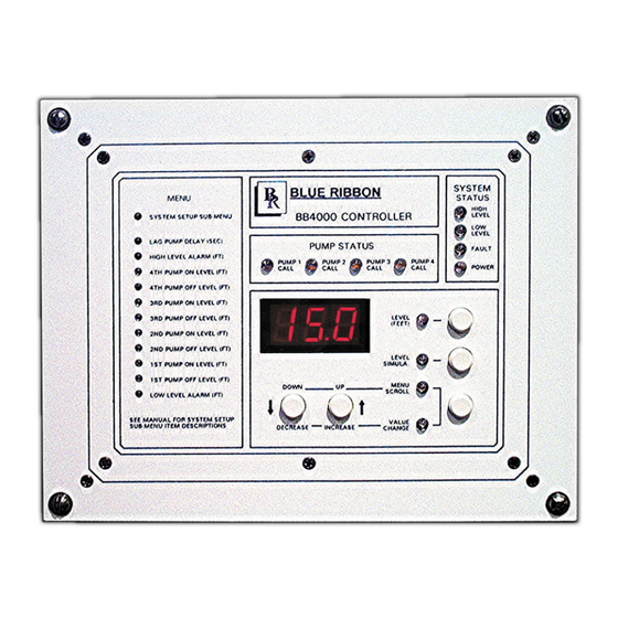
Blue Ribbon BB4000 Quad Pump Controller Manuals
Manuals and User Guides for Blue Ribbon BB4000 Quad Pump Controller. We have
1
Blue Ribbon BB4000 Quad Pump Controller manual available for free PDF download: Instruction Manual
Blue Ribbon BB4000 Instruction Manual (67 pages)
Station Controller
Brand:
Blue Ribbon
| Category:
Controller
| Size: 2 MB
Table of Contents
Table of Contents
2
1 I Ntroduction
7
Applications
7
Standard Features
7
Optional Features
7
Specifications
7
Ordering Information
8
2 O Perator I Nterface F Unctions
9
How to View a Setup Parameter Value
9
How to Change a Setup Parameter Value
9
How to Simulate Levels
10
How to Enter the Security Code
10
1000 M Enu - S Ystem S Etup
12
1000 M Enu - D Ata D Isplay
16
5 P Ump C All S Equence - Setup Parameters
18
Number of Pumps Present - Parameter P .13
18
Number of Pumps Allowed to Run at the same Time - Parameter P .14
18
Number of Pumps Allowed to Run on Generator - Parameter
18
Alternator Sequence Mode - Parameter P .16
19
P Ump C All S Equence
19
S Equence - S Etup P Arameters
19
Pump Stop Mode - Parameter P .17
19
Automatic Alternation - Parameter P .18
20
Forced Lead Pump Position - Parameter P .39
20
Time Based Alternation - Parameter 5.1
20
7 A Lternation S Equence M Ode
21
Standard Alternation
21
Pump 1 Always Lead
21
Pump 1 Always Lead
22
Split Alternation Parameter P .16 = 4
22
Fixed Alternation
23
Stepped On/Off Sequence
23
8 Iscrete I Nput F Unctions
24
Pump 1 (2, 3, 4) Disable - Functions 1-4
24
Level Freeze - Function 5
24
External Alternation - Function 6
24
On Generator - Function 7
25
All Pump Disable - Function 8
25
Sequence Input 1 (2, 3, 4) - Functions 9 - 12
25
Call Pump 1 (2, 3, 4) Last - Functions
25
Low Level Alarm - Function 17
25
High Level Alarm - Function 18
26
Telemetry E - D - Functions 19 - 30
26
Normal Pump Operation Disable - Function 31
26
Float Backup - Lower Level - Function 32
26
Float Backup - off Level - Function 33
27
Float Backup - 1St on Level - Function 34
27
Float Backup - 2Nd on Level - Function 35
27
Float Backup - 3Rd on Level - Function 36
27
Float Backup - 4Th on Level - Function 37
27
Float Backup - High Level - Function 38
28
Start Flush Cycle - Function 39
28
9 S Ystem S Tatus
28
High Level Alarm
28
Low Level Alarm
29
Power Indication
29
Fault Indication
29
Fault Code - Parameter FLC
29
Last Fault Code - Parameter LFC
30
Fault Code Table
31
10 A Nalog L Evel I Nput (4-20 M a I Nput ) - C Alibration P Rocedure
33
Level Input Zero - Parameter P .25
33
Level Input Span - Parameter P .24
33
Level Display Span
34
VS. Transducer Calibration
34
Rive S Peed C
35
VFD Speed Control - Setup Parameters
35
12 F Lush C Ycle
36
Flush Cycle Steps
36
Automatically Starting Flush Cycle
36
Manually Starting / Stopping Flush Cycle
37
Flush Cycle - Setup Parameters
37
13 F Low C Alculator
38
Latest Inflow Rate - the most Recently Determined Flow Rate into the Lift Station
38
Average Daily Inflow Total
38
The Flow Totals from the Last 7 Days Averaged Together
38
Pump Outflow Rate - the most Recently Determined Outflow Rate of each Pump
38
Flow Calculator - Setup Parameters
39
Flow Calculator - Surface Area Calculation
40
Flow Calculator - Display Parameters
40
14 C Ommunication
41
Ith a Scada S Ystem
41
MODBUS Functions Supported
41
Setup for Connection to a SCADA System
41
15 Rs232 S Erial P Ort
42
16 E Thernet
43
Features
43
Setup of Ethernet Port
43
17 Scada R Egisters
44
18 Scada F Eatures
48
Level
48
Discrete Inputs
48
Auxiliary Analog Input Data
49
Pump on / off and Alarm Levels
49
Disabling Pump Operation
49
Forcing a Pump on
49
Setting Speed of Pumps Forced on
50
Forcing Pump Alternation
50
Forcing Lead Pump Position
50
Remote Control of Relays
50
Flush Cycle
51
Flow Calculator Data
51
High Level Telemetry
51
Low Level Telemetry
51
Fault Codes
52
Pump Speed Reference
52
Elapsed Time Meters
52
19 Scada T Rouble S Hooting
52
Communication Activity Indicator
52
Address of Last Slave Polled by Master
53
Record of Last Modbus Message
53
Communication Fault Codes
53
20 C Onnection D Iagram
54
Standard Features
54
Connection Diagram - Optional Analog I/O
55
Connection Diagram - Lead Pump Selector Switch
56
Connection Diagram - Analog Level Input
57
Connection Diagram - Level Probe
58
Level Probe - Placement and Setup
59
Control Schematic Example
60
Float Backup Example - Pump down
61
Operator Interface
63
Enclosure Mechanical Layout
64
Panel Cutout
65
21 W Arranty
66
Advertisement
Advertisement
Related Products
Blue Ribbon BD306
Blue Ribbon BD300
Blue Ribbon BD300-10
Blue Ribbon BD300-11
Blue Ribbon BD300-14
Blue Ribbon BD300-15
Blue Ribbon BD300-13
Blue Ribbon BD300-20X
Blue Ribbon BD300-23X
Blue Ribbon BD300-21X
Blue Ribbon Categories
Transmitter
Controller
Measuring Instruments
More Blue Ribbon Manuals
Login
Sign In
OR
Sign in with Facebook
Sign in with Google
Upload manual
Upload from disk
Upload from URL