Table of Contents
Advertisement
Quick Links
PUBLIC ADDRESS SYSTEM
1
2
3
4
M A
LOW
M A
LOW
M A
LOW
M A
LOW
BUS
CUT
BUS
CUT
BUS
CUT
BUS
CUT
Please follow the instructions in this manual to obtain the optimum results from this unit.
We also recommend that you keep this manual handy for future reference.
5
6
7
8
M A
LOW
M A
LOW
M A
LOW
M A
LOW
BUS
CUT
BUS
CUT
BUS
CUT
BUS
CUT
T-8S02
MIXER PRE-AMPLIFIER
MAIN
AUX
THRESHOLD
RATIO
T-8S02
-20
+20
0
100
ON
OFF
-18 -12 -6
-3
0
+3 +6 +12
LIMIT
HEADPHONE
POWER
Advertisement
Table of Contents
Troubleshooting

Related Manuals for ITC T-8S02


Summary of Contents for ITC T-8S02
- Page 1 PUBLIC ADDRESS SYSTEM T-8S02 MIXER PRE-AMPLIFIER MAIN THRESHOLD RATIO T-8S02 -18 -12 -6 +3 +6 +12 LIMIT HEADPHONE POWER Please follow the instructions in this manual to obtain the optimum results from this unit. We also recommend that you keep this manual handy for future reference.
-
Page 2: Table Of Contents
TABLE OF CONTENTS 1. SAFETY PRECAUTIONS ..................3 2. FEATURES ......................5 3. NOMENCLATURE AND FUNCTIONS 3.1 Front Panel ....................6 3.2 Rear Panel......................7 3.3 Helpful hints....................8 4. INSTALLATION......................9 5.OPERATION......................11 5.1 Troubleshooting Gain Structure...............12 5.2 Recommended Input Wiring Methods..............13 5.3 Fine Tuning....................14 5.4 Compressor/Limiter..................15 5.5 Special Features Activation................16 5.6 Jumper Options....................17 6. -
Page 3: Safety Precautions
1. SAFETY PRECAUTIONS Be sure to read the instructions in this section carefully before use. Make sure to observe the instructions in this manual as the conventions of safety symbols and messages regarded as very important precautions are included. We also recommend you keep this instruction manual handy for future reference. Safety Symbol and Message Conventions Safety symbols and messages described below are used in this manual to prevent bodily injury and property damage which could result from mishandling. - Page 4 SAFETY PRECAUTIONS When the Unit is in Use When Installing the Unit Do not place heavy objects on the unit as this may Never plug in nor remove the power supply plug cause it to fall or break which may result in with wet hands, as doing so may cause electric personal injury and/or property...
-
Page 5: Features
2. FEATURES 1. 8-channel separate switcher inputs. 2. dual lines design with main channel/assistive channel to output selector. 3. each input adopts insert Eroupean terminal. 4. seperate spare input. 5. XLR balance input & output. 6. multi-channel audio source mix up with public bus. 7. -
Page 6: Nomenclature And Functions
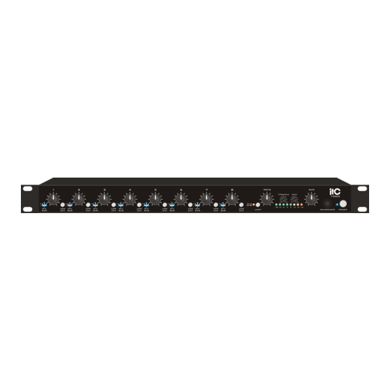
3. NOMENCLATURE AND FUNCTIONS 3.1 FRONT PANEL MAIN THRESHOLD RATIO -18 -12 -6 +3 +6 +12 LIMIT HEADPHONE POWER 10 11 12 Main/Auxiliary Bus Selector (one per channel) A 4-position switch which selects destination of channel input. Input can berouted to: a) the main bus (M-up, A-down);... -
Page 7: Rear Panel
NOMENCLATURE AND FUNCTIONS 3.2 REAR PANEL 17VCT AUX OUT MAIN AUX IN TRIM TRIM TRIM TRIM TRIM TRIM TRIM TRIM PHANTOM POWER -50dB LINE LINE LINE LINE LINE LINE LINE LINE 9 10 1. Ground Connection on Rear Panel Access to ground. 2. -
Page 8: Helpful Hints
NOMENCLATURE AND FUNCTIONS 3.3 Helpful Hints Electrical equipment operates best in a clean, dry, well-ventilated environment free of vibration and electromagnetic fields. The following are some guidelines to achieve optimal performance. Avoid placing the mixer and cables near heat sources. Be particularly aware of other audio equipment, such as amplifiers, which can produce a great deal of heat when operating. -
Page 9: Installation
INSTALLATION Note: Take the mixer out of the box and inspect for shipping damage. If there is obvious physical damage to the outside of the mixer, contact the supplier of the mixer before you begin installation. " Rack Mounting: To mount the CAM8PRO to a 19 rack, lift the unit up to the front of the rack and secure it to the front of the rack with the necessary screws (not included with this unit). - Page 10 INSTALLATION C. Connect Output: Make a connection between Main Bus Output Terminals (3) and an input jack of " " an amplifier. Press Main Output Microphone/Line Switch (2) to appropriate position: for line-level " " output (0dB) or for mic-level (-50 dB) output AUX OUT MAIN PHANTOM...
-
Page 11: Operation
OPERATION The primary goal when establishing the gain settings of the mixers is to have each channel operating at the maximum gain without clipping, while leaving adequate headroom on the volume control knob. The channel Input Gain/Trim Control (1) on the rear panel of the mixers directly controls the microphone pre-amplifier gain available at each channel. -
Page 12: Troubleshooting Gain Structure
OPERATION 5.1 Troubleshooting Gain Structure If the procedure followed to this point does not give satisfactory results, follow the appropriate adjustment sequence below: If channel clipping occurs If the signal is clipping or producing audible distortion, the gain is too high. Reduce the Input Gain/Trim Control (rear panel) by turning it counterclockwise until clipping does not occur. -
Page 13: Recommended Input Wiring Methods
OPERATION 5.2 Recommended Input Wiring Methods These are the best ways to connect sources to the mixer. The mixer input is always balanced. From the drawings below choose the wiring method for your input device (either balanced or unbalanced). Balanced Source to Balanced Input - Method 1 (Normal) Shown below is the normal wiring method for a balanced source device. -
Page 14: Fine Tuning
OPERATION 5.3 Fine Tuning Low Cut Switch To remove excessive bass from an individual channel, press the Low Cut Switch (1) for that channel. This feature helps eliminate low frequency noise (signals of 100 Hz and below, such as background rumble from ventilation systems, etc.) and is used primarily with mic-level input. -
Page 15: Compressor/Limiter
OPERATION 5.4 Compressor/Limiter Low Cut Switch To remove excessive bass from an individual channel, press the Low Cut Switch (1) for that channel. MAIN THRESHOLD RATIO -18 -12 -6 +3 +6 +12 LIMIT The Compressor/Limiter (1) is a dynamic range controller that can be used to compensate for signals that may sound unnatural or cause audible distortion. -
Page 16: Special Features Activation
OPERATION 5.5 Special Features Activation The mixer has several built-in features which are easily activated by making adjustments inside the mixer chassis. Changing the selection of all built-in features requires only the correct placement of internal jumpers or varying the settings of an internal potentiometer. Note: All the internal components-jumpers and potentiometers-to which adjustments are needed for built-in features are highlighted within dashed areas in the drawing below. -
Page 17: Jumper Options
OPERATION 5.6 Jumper Options Changing Jumper Settings To change a jumper setting, remove the ten screws secured to the top of the mixer. After removing the top of the mixer, locate the jumper to be changed by referring to the drawing on page 17. Jumpers are included from the factory in positions: JP1: 1-3, JP2: 2-4,JP3: 1-3, JP4: 1-3, 2-4.. -
Page 18: Troubleshooting Tips
6.TROUBLESHOOTING TIPS NO POWER Check the connections between the mixer and the power supply and the external AC power supply. Examine the 4-pin connector as shown on page 22. Check the wall outlet. NO SOUND Make sure the MIC/Line switch is in the proper position. (This is the most likely cause.) Make sure both the master and channel input controls are turned up. -
Page 19: Glossary
Pot - Potentiometer. " ". RCA Connector - An unbalanced line level connection, also known as phono connector Summing Junction - The point in the T-8S02 circuitry where the audio signals are mixed. -
Page 20: Technical Information
TECHNICAL INFORMATION SPECIFICATIONS Model ................T-8S02 Signal-to-Noise ..............Ref +26dB V @ 54 dB sys gain = 90dB MIC Pre-amp Equivalent Input Noise ........-129dB @ 150 ohm, 20 Hz to 20 kHz Maximum Voltage Gain............96dB Frequency Response ............1dB from 20 Hz to 20 KHz;... -
Page 21: Block Diagram
9. BLOCK DIAGRAM... - Page 22 PUBLIC ADDRESS SYSTEM VersionV0.1...
Need help?
Do you have a question about the T-8S02 and is the answer not in the manual?
Questions and answers