Table of Contents
Advertisement
Quick Links
Advertisement
Table of Contents

Subscribe to Our Youtube Channel
Related Manuals for Geckodrive GM215


Summary of Contents for Geckodrive GM215
- Page 1 GM215 MANUAL STEP MOTOR DRIVE...
-
Page 2: Table Of Contents
Table of Contents Features ............Connector Assignments . - Page 3 Run ............58 Program_Flash_Rom .
-
Page 4: Features
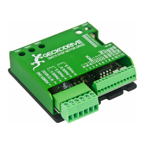
The GM215 is a 7A, 80VDC step motor drive with an integrated motion controller. It can be used as a step and direction input motor drive or as motion control enabled drive. The operating mode and mode related functions are set via the 10-position slide switch on side of the drive. -
Page 5: Connector Assignments
While the motor is turning, adjust TRIM1 for minimum motor vibration. The rest of this user's manual is divided into two sections. Use the GM215 STEP MOTOR DRIVE MANUAL if the GM215 is used as a conventional step motor drive. Use the GM215 MOTION CONTROLLER MANUAL if the GM215 motion controller is used. -
Page 6: Quick Switch Setting Guide
QUICK SWITCH SETTING GUIDE For SW5 to SW10, see NOTE. For more details, see Motor Drive Mode and Motion Controller Mode Switch Settings. = SW is "ON" = SW is "OFF" STEP/DIR full-step (Motor Drive Mode) 1 2 3 4 5 6 7 8 9 10 STEP/DIR half-step (Motor Drive Mode) 1 2 3 4 5 6 7 8 9 10 STEP/DIR 10-microstep (Motor Drive Mode) -
Page 7: Motor Drive Manual
GM215 STEP MOTOR DRIVE MANUAL This manual covers the GM215 when it's used as a conventional STP/DIR input step motor drive. Go to the GM215 MOTION CONTROLLER MANUAL if the GM215 is used as a motion controller and motor drive. -
Page 8: Switch Settings And Connector Wiring
STEP 2: SELECT MOTOR CURRENT Use the following chart to set the GM215 to the motor's phase current rating. If a motor has a rated current that isn't listed in the table below, set the current to the first setting that is greater than the motor's rated current. - Page 9 This step is optional and it can be skipped. Self-Test can also be used after setup is completed or at any other time when it is necessary to verify the GM215 is working correctly. It can be useful when debugging a controller to GM215 interface. When finished with Self-Test, restore switches SW2, SW3, and SW4 to their previous settings to exit the Self-Test routine.
- Page 10 Once the cause for the FAULT is corrected, the FAULT output can be cleared by cycling the power supply or the DISABLE input. When finish switch setup and wiring, it is OK to turn on power supply. END OF GM215 STEP MOTOR DRIVE MANUAL...
-
Page 11: Motion Controller Manual
GM215 MOTION CONTROLLER MANUAL This manual covers the GM215 when it's used as a motion controller and motor drive. Go to the GM215 STEP MOTOR DRIVE MANUAL if the GM215 is used as a conventional STP/DIR input step motor drive. - Page 12 SW2 'ON' In RUN mode, one or more GM215 can execute a user program stored in Flash ROM without requiring a computer connection. NOTE: A RESET/START SWITCH OR BUTTON IS REQUIRED TO USE RUN MODE. See figure 7 – page 16 for more detail.
- Page 13 RS485 (TERMINALS 10, 11, 12) These terminals are used by the RS-485 transceiver. The RS-485 COM terminal connects to the GM215 circuit ground through a 33 Ohm resistor used to limit ground loop currents. All GM215s using the RS-485 serial interface must share a common power supply ground.
- Page 14 The vector component is then processed by a motion control algorithm and the results are sent to the motor drive section of the GM215. Each GM215 then drives its attached axis motor and all the axis motor's movements combine to reconstitute the vector as a 2D or 3D motion in the motor-driven mechanism.
- Page 15 HOME/LIMIT SWITCH WIRING When using command HOME, a hardware connection is a must. Default home switch input is IN2. When using command SPEED CONTROL, it is possible to use two limit switches. Default limit switches input are IN2 and IN3. Figure 6: How to wire the HOME switches...
- Page 16 RUN MODE START/RESET WIRING After flash the on board ROM, GM215 can run at RUN MODE. RUN mode requires a START/RESET button or switch to control the progress. Without it, master and slave drives in a multiple drives system cannot be synchronized well. Default start/reset input is IN1. Once applied a 5v, all drives will be reset and hold the reset status until 5v is released.
-
Page 17: Command Set
The GM215 works as a multiple-axis motion controller when 2 or more drives are connected via its RS-485 interface. When used this way, one GM215 must be named as the X drive (SW3 = ON, SW4 = ON) to make it the master drive. Each of other drives must be set to a unique axis name (Y, Z, or W) using SW3 and SW4. - Page 18 The GeckoMotion host program uses labels for program flow commands. This greatly eases the burden of writing and debugging the user program: 00067 PREVIOUS COMMAND 00068 IF Z INPUT 2 IS OFF GOTO label_1 An IF command tests if the Z axis input 2 is off. If true, the program jumps to 'label_1:' 00069 NEXT COMMAND...
-
Page 19: Configure Axis
________________________________________________________________________________________________________ CONFIGURE AXIS CONFIGURATION COMMAND Syntax: CONFIGURE: AMPS, IDLE AT % AFTER s SECONDS<ENTER> Operands: = X, Y, Z, W CONFIGURE = configure axis command 0.0 <= <= 7.0 00 <= < 100 00.0 <= =< 25.5 Operation: Sets the motor's operating parameters. Type: The command settings are global. -
Page 20: Vector Axis
________________________________________________________________________________________________________ VECTOR AXIS CONFIGURATION COMMAND Syntax: VECTOR AXIS ARE a, a, a, a <ENTER> Operands: = axis Operation: Associates which axis are to be combined for vector motion. Type: The command settings are global. Description: This command selects which axis will be combined for vector motion. Vector velocity is the same regardless of the vector's direction, all associated axis motion begins and ends at the same time and the path taken will be a straight line connecting the origin and destination coordinates. -
Page 21: Zero Offset
________________________________________________________________________________________________________ ZERO OFFSET CONFIGURATION COMMAND Syntax: ZERO OFFSET n <ENTER> Operands: = axis 0 <= <= 8,388,607 Operation: Sets the axis 'zero' position CW from the HOME switch. Type: The command settings are global. Description: The command value is used by the HOME command to automatically move the axis CW from the HOME switch location a distance equal to the ZERO OFFSET value. -
Page 22: Velocity
________________________________________________________________________________________________________ VELOCITY CONFIGURATION COMMAND Syntax: n<ENTER> VELOCITY n<ENTER>) Operands: = axis VEL = VELOCITY command 0 <= <= 32767 Operation: Sets the axis velocity limit. Type: The command settings are global. Description: The motor will accelerate at a rate set by the ACCELERATE command to a speed set by the VELOCITY command. If the VELOCITY value is changed while the motor is running, the motor will accelerate or decelerate to the new VELOCITY value. -
Page 23: Move
________________________________________________________________________________________________________ MOVE MOTION COMMAND Syntax: asn, asn, asn, asn<ENTER> Operands: = axis – <SP> 0 =< <=16,777,215 for <SP> 0 =< <=8,388,607 for – Operation: Moves the listed axis to positions set by the n value. Type: The command settings are local. Description: Because this command is likely to be used far more frequently than any other command, the number of keystrokes to enter this command are kept to an absolute minimum. -
Page 24: Home
________________________________________________________________________________________________________ HOME MOTION COMMAND Syntax: HOME a, a, a, <ENTER> Operands: HOME = HOME command a = axis Operation: Moves the listed axis to the HOME switch location. Type: The command's OFFSET value is global. Description: The HOME command moves the selected axis CCW towards a HOME switch connected to IN2. The axis acceleration rate is the ACELERATE command value and velocity set by the VELOCITY command value. -
Page 25: Jog
________________________________________________________________________________________________________ MOTION COMMAND Syntax: a, a, a, <ENTER> Operands: a = axis Operation: Move the axis using switches or trimpots. Dependence: ANALOG INPUT command. Type: The command requires a hardware exit. Description: If the ANALOG INPUT command doesn't include the axis, the JOG command uses IN2 as the JOG CW switch input and IN3 as the JOG CCW switch input. -
Page 26: Speed Control
________________________________________________________________________________________________________ SPEED CONTROL MOTION COMMAND Syntax: SPEED CONTROL sn <ENTER> Operands: <= n <= 32767 Operation: The axis runs continuously at set speeds. Dependence: ANALOG INPUT, ACCELERATE and VELOCITY command values. Type: The command requires a hardware exit. Description: This is special 'canned' command that runs the axis continuously at a set speed. IN1 can be connected to a Stop/Run button, and CW/CCW travel distance limit switches can be used with IN2 and IN3 to change motor direction. -
Page 27: Position Adjust
________________________________________________________________________________________________________ POSITION ADJUST MOTION COMMAND Syntax: POSITION ADJUST +/- n <ENTER> Operands: 0 =< n <= 32,767 Operation: Adjusts the axis position using an analog voltage. Dependence: None Type: The command requires a hardware exit. Description: This command uses TRIM5 to adjust the axis position within a CW / CCW range set by the n value. The TRIM5 setting adjusts the axis position over a +/- 100% range of the n value;... -
Page 28: Goto
PROGRAM FLOW COMMANDS: Program flow commands break the normal sequential order of program flow by forcing an out of sequence location of the next command. Commands then execute sequentially again starting at the new location. The main program flow commands are unconditional jumps and loops (GOTO), calls and returns from subroutines (CALL), If-Then-Else conditional jumps (IF) and wait loops (PAUSE). -
Page 29: Call
________________________________________________________________________________________________________ CALL PROGRAM FLOW COMMAND Syntax: CALL k <ENTER> Operands: k = <LABEL> Operation: Calls a function. Returns to the program line after this one when finished. Dependence: None Type: The command value is local. Description: This command jumps from the current command line to a command line specified by the value n. The program continues from that line until the function is finished. -
Page 30: Return
________________________________________________________________________________________________________ RETURN PROGRAM FLOW COMMAND Syntax: RETURN <ENTER> Operands: None Operation: Returns to the program line after the CALL command line. Dependence: None Type: The command value is local. Description: This command is used to end a CALL function. The program counter jumps to the next program line after the CALL command line. -
Page 31: If-Then-Else
COMPARE value (see COMPARE command). VIN is a 1-byte analog to digital conversion of a 0V to 5V input to the GM215. VEL is a 2-byte value of the axis's current velocity and POS is a 3-byte value of the axis' current position. - Page 32 Assume X axis output 3 must be turned 'on' if the Z axis voltage on VIN is between 2.5V and 3.0V. PGM LINE COMMAND COMMENT 00455 COMPARE VALUE 256 times 3.0V divided by 5.0V 00456 Z VIN > GOTO out3_off GOTO label out3_off if VIN is greater than 3V.
-
Page 33: Output
________________________________________________________________________________________________________ OUTPUT MISCELLANEOUS COMMAND Syntax: n c <ENTER> Operands: a = X or axis name c = ON, OFF, BR, RS, ER Operation: Outputs OUT1 or OUT2 or OUT3 Dependence: None Type: The command value is local. Description: Turns a hardware output ON or OFF Examples: 3 ON <ENTER>... -
Page 34: Example Code
EXAMPLE CODE: EXAMPLE 0: MOVE A MOTOR x configure: 1 amps, idle at 50% after 1 seconds x limit cw 100000 x offset 1000 analog inputs to {0} ; NO AXIS USING ANALOG vector axis are {0} ; NO AXIS USING VECTOR x acceleration 64 ;... - Page 35 EXAMPLE 2: BASIC VECTOR MOTION x_config: x configure: 1 amps, idle at 50% after 1 seconds x limit cw 12000000 x offset 1000 y_config: y configure: 1 amps, idle at 50% after 1 seconds y limit cw 12000000 y offset 1000 start: x acceleration 512 ;...
- Page 36 EXAMPLE 3: POINT TO POINT MOTION, SPEED CONTROLLED BY TRIMPOT (ANALOG) x_config: x configure: 1 amps, idle at 50% after 1 seconds x limit cw 12000000 x offset 1000 y_config: y configure: 1 amps, idle at 50% after 1 seconds y limit cw 12000000 y offset 1000 start:...
- Page 37 EXAMPLE 4: RUN MOTION UNDER ABSOLUTE POSITION SYSTEM x_config: x configure: 1 amps, idle at 50% after 1 seconds x limit cw 12000000 x offset 1000 y_config: y configure: 1 amps, idle at 50% after 1 seconds y limit cw 12000000 y offset 1000 start: x acceleration 512...
- Page 38 EXAMPLE 5: USING JOG COMMAND x_config: x configure: 1 amps, idle at 50% after 1 seconds x limit cw 12000000 x offset 1000 start: x acceleration 512 ; GO HOME ACCELERATION x velocity 1000 ; GO HOME VELOCITY home x ;...
- Page 39 EXAMPLE 8: USING POSITION ADJUST COMMAND x_config: x configure: 1 amps, idle at 50% after 1 seconds x limit cw 12000000 x offset 1000 start: x acceleration 512 ; GO HOME ACCELERATION x velocity 1000 ; GO HOME VELOCITY home x ;...
- Page 40 EXAMPLE 10: USING ANALOG INPUT AND COMPARE COMMAND x configure: 1 amps, idle at 50% after 1 seconds x limit cw 100000 x offset 1000 analog inputs to {0} ; NO AXIS USING ANALOG vector axis are {0} ; NO AXIS USING VECTOR x acceleration 64 ;...
- Page 41 NOTE: THIS IS JUST AN EXPLORATION OF POSSIBLE NEW COMMANDS. ________________________________________________________________________________________________________ MOVING AVERAGE FILTER CONFIGURATION COMMAND Syntax: MOVING AVERAGE a, a, a, a n SAMPLES <ENTER> Operands: a = axis X or Y or Z or W 0 < n <=127 Operation: Associates which axis are moving average filtered.
- Page 42 ________________________________________________________________________________________________________ GROUP AXIS CONFIGURATION COMMAND Syntax: GROUP A IS ad ad ad a AXIS <ENTER> Operands: G = GROUP command a = axis X and Y and Z and W in that order d = , or <SP> Operation: Assigns axis to groups Description: The GROUP command assigns the axis to groups that have common function and each member axis in a group runs from the same user program.
- Page 43 ________________________________________________________________________________________________________ CHANGE SCALE MISCELLANEOUS COMMAND ________________________________________________________________________________________________________ ROTATE MISCELLANEOUS COMMAND ________________________________________________________________________________________________________ ENCODER MISCELLANEOUS COMMAND ________________________________________________________________________________________________________ TANGENT MOTION COMMAND...
-
Page 44: Edit Mode
USING THE GM215 MOTION CONTROLLER ________________________________________________________________________________________________________ The EDIT MODE is used to write, debug or read back the user program to and from the GM215. To use the EDIT mode, user needs to do the followings: Download GeckoMotion Controller and Configuration Software by using this link: http://www.geckodrive.com/support/geckomotion.html... - Page 45 Figure 8: Device Error window 3.2 Python window GeckoMotion window description: Figure 9: Python window Python window is used to display communication activities and status such as sent command, feedback data, error message, etc. To close this window will terminate GeckoMotion program.
- Page 46 Set the Settings in tab pages as followings: - Target: Select GM215 or GM215-1 for 3in-3out model, select GM215-2 for 4in-2out model. Log all communications: Set to OFF for this moment. Serial port: Select the available port for this RS485 interface.
-
Page 47: Create, Save And Open A Program
4) Create a program using GeckoMotion: 4.1 Create a new program: - In the menu, click File and then select New. A new tab will be inserted next to Settings tab with the name <untitled>. - Click at <untitled> tab to open it and write a program (or copy-paste from other text editor). For example: Figure 11: How to create a new file. - Page 48 Figure 12: How to save and rename a file. File name <untitled> will be replaced by Testfile. 4.3 To close a file: Click at X after the file name to close the file. Example: In Figure 11, click at X after <untitled> will close <untitled>. 4.4 Reopen the file: In the menu, click File and then select Open.
-
Page 49: Compile And Run A Program
Figure 13: How to open a file. 5) Run a program: Use the program in Figure 11 for this section. 5.1 Compile a program: To run a program, user needs to compile it first. - Open the file (see section 4.4). - Click at file name to open the file. -
Page 50: Step A Program For Testing/Troubleshooting
Settings GeckoMotion window and set Log all communications to ON. This will enable the feedback and print all sent commands and its feedback from GM215 on Python window. - Click Estop button to reset program counter to the beginning of the program. Line 1 of the program should be highlighted: x configure: 0.5 amps, idle at 71% after 2.5 seconds... -
Page 51: 6.1 Program Flash Memory
GM215 on Python window. - Click Flash button to download the program to the flash memory of the GM215. The following message will be displayed: Figure 16: Flash Progress window Program content will be printed on Python window with “Programming complete”... -
Page 52: Input Simulation
04 00 05 0E 19 47 x configure: 0.5 amps, idle at 71% after 2.5 This line can be sent to the GM215 to execute commands “ seconds”. User should add 1ms delay after each line to avoid buffer overflow if the program is longer than 32 bytes. -
Page 53: Using Other Serial Communication Programs
10) Using other Serial Communication Programs (not GeckoMotion): All other serial communication programs such as Hyperterminal, RealTerm, Serial Port Unitlity, etc., or user’s own program can be used to control the GM215 with the following setup and protocol: Setup: - Set Port to available COM port for this RS485 interface. - Page 54 +5000) These 2 lines can be sent to the GM215 to execute commands “x velocity 1000” and “x +5000”. User should add 1ms delay after each line to avoid buffer overflow if the program is longer than 32 bytes.
- Page 55 Figure 21: Using Serial Port Utility for motor control.
-
Page 56: Appendix A: Run Mode
STATUS from each drive provides this information. Finally, the STATUS also informs all drives of an ERROR condition in any drive. THE USER PROGRAM MUST LOOP-BACK ON ITSELF: The GM215 drive or drives are attached to a mechanism that is driven by a motor or motors. In most cases the mechanism... -
Page 57: Appendix B: Edit Mode
1) Writing, testing and debugging a user program 2) Programming the flash memory with the user program 3) Loading GM215 firmware updates. In the EDIT mode all drives switch to their crystal oscillators and the host PC UART becomes the master. As master, only the host can initiate transmissions over the RS-485 bus. -
Page 58: Run
The sent user command is not stored to the attached GM215 flash memories. The ADDRESS is used by the guest axis to calculate the next user command address. If executing the user command doesn't change program flow then the calculated address will be the host-sent ADDRESS + 1. -
Page 59: Program_Flash_Rom
PROGRAM_FLASH_ROM Description: After successfully compiled, user can download the program to the flash memory on board. The PC should send 0x0005 first and then start to send the data stream. See Appendix C or contact Geckodrive for more details. ________________________________________________________________________________________________________... -
Page 60: Query_Short
QUERY_SHORT EDIT MODE COMMAND QUERY_LONG EDIT MODE COMMAND Syntax: 0x0007 for QUERY_SHORT 0x0008 for QUERY_LONG Description: The QUERY_LONG command updates each axis' inputs, outputs, position, velocity, errors and Busy/Ready status. This can be used as a near real-time update if the host sends the LONG_QUERY command repeatedly. Each axis will immediately reply with a 10-byte block of data for each axis. -
Page 61: Load_Program_Counter
W 5000 When this motion command finishes execution, the X axis GM215 updates its program counter to the next user program address, in this case its 0xA93D. The next QUERY shows this update and the host uses this address to fetch the next user command. -
Page 62: Appendix C: Command Format
APPENDIX C: COMMAND FORMAT The rest of this section describes how the user commands are converted from text to binary machine language format. COMMAND FORMAT: 2 words are used to form a command, here called HIGH WORD and LOW WORD. The upper byte of the HIGH WORD contains a 5-bit command op-code and a 3-bit sub-command. - Page 63 _______________________________________________________________________________________________________ MOVE op-code 0x00 MOTION COMMAND EXAMPLE: X 255 <ENTER> H=0000, L=00FF (hex value) Y 65535 <ENTER> H=4000, L=FFFF Z 16777215 <ENTER> H=80FF, L=FFFF X 15, Y 255, Z 4095, W 65535 <ENTER> H=2000, L=000F (X COORDINATE) H=6000, L=00FF (Y COORDINATE) H=A000, L=0FFF (Z COORDINATE) H=C000, L=FFFF...
- Page 64 ________________________________________________________________________________________________________ HOME op-code 0x02 MOTION COMMAND EXAMPLE: HOME X <ENTER> H=0200, L=0000 HOME X, Y, Z, W <ENTER> H=2200, L=0000 (X COORDINATE) H=6200, L=0000 (Y COORDINATE) H=A200, L=0000 (Z COORDINATE) H=C200, L=0000 (W COORDINATE _______________________________________________________________________________________________________ GOTO op-code 0x03 PROGRAM FLOW COMMAND EXAMPLE: GOTO CW_MOTION, LOOP 8 TIMES <ENTER>...
- Page 65 ________________________________________________________________________________________________________ CALL op-code 0x04 PROGRAM FLOW COMMAND EXAMPLE: CALL X_CONFIG <ENTER> H=0400, L=000C (if X_CONFIG address is at 000C) ________________________________________________________________________________________________________ IF-THEN-ELSE op-code 0x05 PROGRAM FLOW COMMAND EXAMPLE: IF X IN1 IS ON GOTO LOOP1 <ENTER> H=0520, L=000D (if LOOP1 address is at 000D) IF Y RDY IS OFF GOTO LOOP1 <ENTER>...
- Page 66 ________________________________________________________________________________________________________ OUTPUT op-code 0x06 MISCELLANEOUS COMMAND EXAMPLE: X OUT 1 ON <ENTER> H=0611, L=0000 Y OUT 2 BR <ENTER> H=4622, L=0000 Z OUT 3 RS <ENTER> H=8633, L=0000 W OUT 1 ER <ENTER> H=C614, L=0000 ________________________________________________________________________________________________________ VELOCITY op-code 0x07 CONFIGURATION COMMAND EXAMPLE: X VEL 255 <ENTER>...
- Page 67 ________________________________________________________________________________________________________ 0x08 WAIT op-code PROGRAM FLOW COMMAND EXAMPLE: WAIT 0.255 SECONDS <ENTER> H=0800, L=00FF WAIT 1.234 SECONDS <ENTER> H=0800, L=04D2 WAIT 65.535 SECONDS <ENTER> H=0800, L=FFFF ________________________________________________________________________________________________________ MOVING AVERAGE FILTER op-code 0x09 CONFIGURATION COMMAND EXAMPLE: MOVING AVERAGE X, Y, Z 100 SAMPLES <ENTER>...
- Page 68 ________________________________________________________________________________________________________ ANALOG INPUTS op-code 0x0A CONFIGURATION COMMAND EXAMPLE: ANALOG INPUT X <ENTER> H=0A01, L=0000 ANALOG INPUT X, Y <ENTER> H=0A03, L=0000 ANALOG INPUT X, Y, Z, W <ENTER> H=0A0F, L=0000 ________________________________________________________________________________________________________ VECTOR AXIS op-code 0x0B CONFIGURATION COMMAND EXAMPLE: VECTOR AXIS ARE X <ENTER>...
- Page 69 ________________________________________________________________________________________________________ ACCELERATION op-code 0x0C CONFIGURATION COMMAND EXAMPLE: X ACCELERATION 255 <ENTER> H=0C00, L=00FF Y ACCELERATION 32767 <ENTER> H=4C00, L=7FFF ________________________________________________________________________________________________________ SPEED CONTROL op-code 0x0D MOTION COMMAND EXAMPLE: X SPEED CONTROL 15 <ENTER> H=0D00, L=000F Y SPEED CONTROL +255 <ENTER> H=4D00, L=00FF Z SPEED CONTROL +32767 <ENTER>...
- Page 70 ________________________________________________________________________________________________________ CONFIGURE AXIS op-code 0x0E CONFIGURATION COMMAND EXAMPLE: X CONFIG: 0.1 AMPS, IDLE AT 0% AFTER 0.0 SECONDS <ENTER> H=0E01, L=0000 Y CONFIG: 1.5 AMPS, IDLE AT 15% AFTER 1.5 SECONDS <ENTER> H=4E0F, L=0F0F Z CONFIG: 7.0 AMPS, IDLE AT 99% AFTER 25.5 SECONDS <ENTER>...
- Page 71 ________________________________________________________________________________________________________ POSITION ADJUST op-code 0x10 CONFIGURATION COMMAND EXAMPLE: X POSITION ADJUST +/- 255 <ENTER> H=1000, L=00FF Y POSITION ADJUST +/- 32767 <ENTER> H=5000, L=7FFF ________________________________________________________________________________________________________ op-code 0x11 MOTION COMMAND EXAMPLE: JOG X <ENTER> H=1101, L=0000 JOG X, Y <ENTER> H=1103, L=0000 JOG X, Y, Z, W <ENTER>...
- Page 72 ________________________________________________________________________________________________________ RETURN op-code 0x12 PROGRAM FLOW COMMAND EXAMPLE: RETURN <ENTER> H=1200, L=0000 ________________________________________________________________________________________________________ ZERO OFFSET op-code 0x13 CONFIGURATION COMMAND EXAMPLE: X ZERO OFFSET 255 <ENTER> H=1300, L=00FF Y ZERO OFFSET 65535 <ENTER> H=5300, L=FFFF Z ZERO OFFSET 16777215 <ENTER> H=93FF, L=FFFF...
- Page 73 ________________________________________________________________________________________________________ COMPARE op-code 0x14 MISCELLANEOUS COMMAND EXAMPLE: X COMPARE VALUE 255 <ENTER> H=1400, L=00FF Y COMPARE VALUE 65535 <ENTER> H=5400, L=FFFF Z COMPARE VALUE 16777215 <ENTER> H=94FF, L=FFFF ________________________________________________________________________________________________________ RESPOS op-code 0x15 MOTION COMMAND EXAMPLE: RESPOS X <ENTER> H=1501, L=0000 RESPOS X, Y <ENTER>...
-
Page 74: Appendix D: More Sample Code
;SET UP: ; 1. TURN POWER OFF ; 2. CONNECT THE GM215 WITH A FREE-RUNNING MOTOR. ; 3. USE 3 MOMENTARY SWITCHES (SW1, SW2, SW3). CONNECT ONE SIDE OF THE SWITCHES TO IN1, IN2, IN3 AND CONNECT THE OTHER SIDE OF THE SWITCHES TO AN EXTERNAL +5VDC (WITH GROUND CONNECTED TO CN2-PIN4). -
Page 75: Speed Control
;SET UP: ; 1. TURN POWER OFF ; 2. CONNECT THE GM215 WITH A FREE-RUNNING MOTOR. ; 3. USE 2 MOMENTARY SWITCHES (SW2, SW3). CONNECT ONE SIDE OF THE SWITCHES TO IN2 & IN3 AND CONNECT THE OTHER SIDE OF THE SWITCHES TO AN EXTERNAL +5VDC (WITH GROUND CONNECTED TO CN2-PIN4). -
Page 76: Position Adjust
;SET UP: ; 1. TURN POWER OFF ; 2. CONNECT THE GM215 WITH A FREE-RUNNING MOTOR. ; 3. USE 1 MOMENTARY SWITCH FOR SW1. CONNECT ONE SIDE OF SW1 TO IN1 AND CONNECT THE OTHER SIDE OF THE SW1 TO AN EXTERNAL +5VDC (WITH GROUND CONNECTED TO CN2-PIN4). -
Page 77: Respos X
;SET UP: ; 1. TURN POWER OFF ; 2. CONNECT THE GM215 WITH A FREE-RUNNING MOTOR. ; 3. USE 2 MOMENTARY SWITCHES (SW2, SW3). CONNECT ONE SIDE OF THE SWITCHES TO IN2, IN3 AND CONNECT THE OTHER SIDE OF THE SWITCHES TO AN EXTERNAL +5VDC (WITH GROUND CONNECTED TO CN2-PIN4). -
Page 78: Appendix E: Error Code And Fuse Replacement
APPENDIX E: ERROR CODE and FUSE REPLACEMENT (Error code is for GM215 with FPGA version 2 or later) LED1 and LED2 are used to display error code for the system. LED1 is the combination of 2 different LEDs for displaying 2 colors: red and green. -
Page 79: Appendix F: Update Firmware
- Download or copy ds30LoaderGui.exe to a directory. This file can be downloaded from Geckodrive website. - Connect the GM215 with host PC by using a RS-485 cable. Disconnect all devices except for the target device. - Set SW1-SW4 to ON position Firmware can be updated in two different ways with or without GeckoMotion. - Page 80 4. Go to section to continue (Figure 25). C (DS30 LOADER GUI) WITHOUT GECKOMOTION: The ds30 Loader GUI does not require to be installed, it can be run directly from the bin director. 1. WINDOWS: - Double click ds30LoaderGui.exe from Explorer - Use run on the start menu, browse to ds30LoaderGui.exe - Start from command prompt Go to section...
- Page 81 4) Select Hex-file: in Hex-file box, select the file to be updated. This file can be downloaded from Geckodrive web. After the file is selected, “Hex file successfully parsed” will be displayed on the output text box (see Fig 20).
-
Page 82: Appendix G: Inputs And Outputs Interface
APPENDIX G: INPUTS and OUTPUTS INTERFACE Figure 26: Inputs/Outputs Interface... -
Page 83: Mechanical Switch Interface
Figure 27: Mechanical Switch Interface... -
Page 84: Inductive Switch Interface
Figure 28: Inductive Switch Interface... -
Page 85: Optical Switch Interface
Figure 29: Optical Switch Interface... -
Page 86: Hall Effect Switch Interface
Figure 30: Hall Effect Switch Interface... -
Page 87: Disclaimer, Manual Change Log - Manual
GECKODRIVE INC. assumes no liability for applications assistance or the purchaser’s product design. GECKODRIVE INC. does not warrant or represent that any license, either express or implied, is granted under any patent right, copyright or other intellectual property right of GECKODRIVE INC.
Need help?
Do you have a question about the GM215 and is the answer not in the manual?
Questions and answers