Table of Contents
Advertisement
Quick Links
Advertisement
Chapters
Table of Contents

Related Manuals for Viessmann Vitosorp 200-F


Summary of Contents for Viessmann Vitosorp 200-F
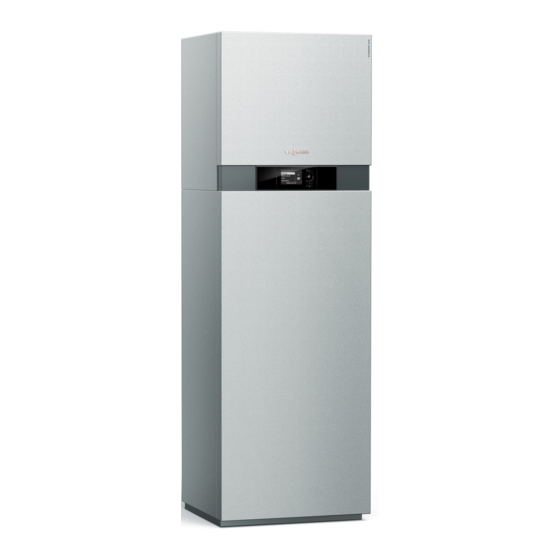
- Page 1 VIESMANN Installation and service instructions for contractors Vitosorp 200-F Type D2RA, 1.8 to 16.7 kW Gas adsorption heating appliance Natural gas and LPG version For applicability, see the last page VITOSORP 200-F Please keep safe. 5678 044 GB 09/2016...
- Page 2 Statutory regulations for environmental protection For replacements, use only original spare parts ■ Codes of practice of the relevant trade associations supplied or approved by Viessmann. ■ All current safety regulations as defined by DIN, EN, DVGW, TRGI, TRF, VDE and all locally applicable...
- Page 3 Safety instructions Safety instructions (cont.) What to do if you smell flue gas Danger The simultaneous operation of the boiler and Danger appliances that extract air to the outside can Flue gas can lead to life threatening poisoning. result in life threatening poisoning due to ■...
-
Page 4: Table Of Contents
Index Index 1. Information Disposal of packaging ................Symbols ....................Intended use ..................Product information ................Condensing module ................■ Sorption module ................. ■ Accessories required (order separately) ..........■ 2. Preparing for installation Installation preparations ................. 10 Transportation ..................10 ■... - Page 5 ■ Setting the control valve motor position ..........106 Checking the temperature sensors ............107 Temperature sensor overview ............107 ■ Curves for Viessmann NTC 10 k ............108 Ω ■ Fault "A3" on first heat demand after commissioning ......108 Checking the pressure sensor ............... 108 Checking the secondary circuit temperature limiter .......109...
- Page 6 Index Index (cont.) Internal extensions (accessories) ............140 Internal H1 extension ................140 ■ Internal H2 extension ................140 ■ External extensions (accessories) ............141 AM1 extension ..................141 ■ EA1 extension ..................142 ■ Control functions ..................143 External operating program changeover ..........143 ■...
- Page 7 Please dispose of packaging waste in line with statu- DE: Use the disposal system organised by tory regulations. Viessmann. AT: Use the ARA statutory disposal system (Altstoff Recycling Austria AG, licence number 5766). CH: Packaging waste is disposed of by the HVAC contractor.
- Page 8 Product information The Vitosorp 200-F, type D2RA is a hybrid appliance A plate heat exchanger and safety valve provide inte- consisting of a condensing module and a sorption gral system separation for the heating circuit and proc- module.
- Page 9 Information Product information (cont.) For solar thermal systems: ■ Solar pack with collectors and combi cylinder ■ Solar thermal cylinder pack for retrofitting to an exist- ing solar thermal system For geothermal heat: Accessories for primary circuit (e.g. brine circuit ■...
-
Page 10: Installation Preparations
Preparing for installation Installation preparations Transportation Please note Please note Tilting at a steep angle will damage the sorption Impact, compression and tensile loads can module of the gas adsorption heating appliance. cause damage to the outside panels of the It is essential that the maximum tilting angle is appliance. -
Page 11: Preparations For Installing The Appliance
Preparing for installation Installation preparations (cont.) Please note Align the appliance horizontally. ■ Overloading the floor can result in damage to If the adjustable feet are used to compensate for an the building structure. uneven floor (max. 30 mm), the pressure load on the Observe the permissible floor load. - Page 12 Preparing for installation Installation preparations (cont.) Fig. 2 Heating flow R Safety valve discharge pipe to the rear and into the ¾ DHW cylinder flow R wall, to the left or to the right ¾ Primary circuit flow (natural heat source inlet) G Gas connection R ½...
- Page 13 Preparing for installation Installation preparations (cont.) Preparing connections on the primary side Natural heat source Geothermal energy – brine heat Geothermal energy – water heat Solar thermal transfer medium transfer medium We recommend that you use the We recommend that you use the With a combi cylinder: ■...
- Page 14 Preparing for installation Installation preparations (cont.) Preparing connections on the secondary side Danger Incorrectly executed electrical installations can ■ Thoroughly flush the heating system. result in injuries from electrical current and dam- ■ Equip the heating system with an expansion vessel age to the appliance.
-
Page 15: Siting The Appliance
Installation sequence Siting the appliance Removing the side panels Note The front and side panels can be removed for easier handling. Fig. 3... -
Page 16: Fitting The Condensing Module On The Sorption Module
Installation sequence Siting the appliance (cont.) Fitting the condensing module on the sorption module 3. 3x Fig. 4... - Page 17 Installation sequence Siting the appliance (cont.) Fig. 5 Special grease for step 7 and screws for step 8 are included in the standard delivery 07. Lubricate the O-rings with the special grease sup- 10. Open the Vitotronic control unit: see page 26. plied.
- Page 18 Installation sequence Siting the appliance (cont.) 15. 3x sÖ Fig. 6 14. Push slide couplings up far enough to enable fastening clips to be fitted correctly. Fitting slide couplings incorrectly can cause water to escape and can damage the appliance.
-
Page 19: Connections On The Primary Side
Installation sequence Connections on the primary side Please note Mechanically strained hydraulic connections lead to leaks and appliance damage. Connect on-site lines so that they are free of load and torque stress. Connecting supplied pipe sections to the sorption module Fig. -
Page 20: Connections On The Secondary Side
Installation sequence Connections on the secondary side Please note Mechanically strained hydraulic connections lead to leaks and appliance damage. Connect on-site lines so that they are free of load and torque stress. For connections on the cylinder side, the intermediate pieces of the connection set (accessories) must be replaced. -
Page 21: Condensate Connection
Installation sequence Connections on the secondary side (cont.) Fig. 9 Heating flow R ¾ DHW cylinder flow R ¾ DHW cylinder return R ¾ Heating return R ¾ Condensate connection 2. Route condensate hose and safety valve dis- charge pipe to the rear to the wall, or to the left or right to the side aperture. -
Page 22: Aligning The Appliance
Installation sequence Condensate connection (cont.) The condensate hose and safety valve discharge Observe local waste water regulations. ■ pipe are separate pipes. The pipes meet the temper- ature requirements for CE certification. Note ■ We recommend connecting the condensate hose Fill the trap with water before commissioning. -
Page 23: Flue Gas Connection
■ Applicable regulations on installing and commission- mentation. These labels may be used only in con- ing flue systems have been followed. junction with the Viessmann flue system made by Skoberne. Danger During installation and positioning of the flue system, Leaking or blocked flue systems or an insuffi- ■... -
Page 24: Electrical Connections
Installation sequence Electrical connections Danger Danger Damaged wiring insulation can lead to serious The absence of system component earthing can injury from electrical current and result in appli- lead to serious injury from electrical current and ance damage. component damage in the event of an electrical Route cables so that they cannot come into con- fault. -
Page 25: Solar Thermal System In Conjunction With Combi Cylinder And Primary Thermal Store
Installation sequence Electrical connections (cont.) Fig. 15 Solar thermal system in conjunction with combi cylinder and primary thermal store Note In conjunction with a separate primary thermal store (e.g.Vitocell 140-E), a 3-way diverter valve (accesso- ries) must be connected to solar module SM1 (acces- sories). -
Page 26: Opening The Vitotronic Control Unit
Installation sequence Electrical connections (cont.) Opening the Vitotronic control unit Please note Electronic assemblies can be damaged by elec- trostatic discharge. Prior to commencing any work, touch earthed objects such as heating or water pipes to dis- charge static loads. Fig. -
Page 27: Routing Flexible Cables To The Wiring Chamber Of The Vitotronic Control Unit
Installation sequence Electrical connections (cont.) Routing flexible cables to the wiring chamber of the Vitotronic control unit Cables: Required cable length inside the appliance plus dis- ■ tance to wall: 1400 mm ■ Height of wall outlet: 1160 mm < 42 V 230 V~ <... -
Page 28: Overview Of Electrical Connections In The Vitotronic Control Unit
Installation sequence Electrical connections (cont.) Overview of electrical connections in the Vitotronic control unit Fig. 18 Jumper Connections to 230 V~ plugs KM-BUS subscriber (accessories) Secondary pump (see page 18) To connect several accessories, see page 31 sÖ Power supply ■... -
Page 29: Outside Temperature Sensor
Installation sequence Electrical connections (cont.) Outside temperature sensor For fitting the wireless outside temperature sensor Not immediately below balconies or gutters ■ (wireless accessory): ■ Never render over Wireless base station installation and service Outside temperature sensor connection instructions 2-core lead, length max. 35 m with a cross-section of Fitting location for outside temperature sensor 1.5 mm ■... -
Page 30: External Blocking Via Switching Contact
Installation sequence Electrical connections (cont.) Ensure DC separation between the earth conductor 0 to 1 V No specification for set boiler water and the negative pole of the on-site power source. temperature Set value 10 °C 10 V Set value 100 °C [{{] fÖ... -
Page 31: Connecting Accessories To The Mains At Plug
Installation sequence Electrical connections (cont.) Connecting accessories to the mains at plug (230 V~) in the Vitotronic control unit Where the boiler is sited in a wet room, accessories If the total system current exceeds 6 A, connect one or outside the wet area must not be connected to the more extensions directly to the mains supply via an power supply at the control unit. -
Page 32: Power Supply Fö
Installation sequence Electrical connections (cont.) Power supply fÖ Danger Install an isolator in the power cable to provide ■ Incorrectly executed electrical installations can omnipolar separation from the mains for all active result in injuries from electrical current and in conductors, corresponding to overvoltage cate- appliance damage. -
Page 33: Closing The Vitotronic Control Unit And Inserting The Programming Unit
Installation sequence Electrical connections (cont.) Closing the Vitotronic control unit and inserting the programming unit Fig. 23 Insert the programming unit (packed separately) into Wall mounting base installation instructions the control unit support. Note The programming unit can also be inserted into a wall mounting base (accessories) close to the appliance. -
Page 34: Fitting The Front Panels
Installation sequence Fitting the front panels 5. 5. Fig. 24... -
Page 35: Steps - Commissioning, Inspection And Maintenance
Commissioning, inspection, maintenance Steps - commissioning, inspection and maintenance Commissioning steps Inspection steps Maintenance steps Page • • • 1. Removing the front panels....................37 • 2. Checking the power supply • • 3. Filling and venting the primary circuit................37 •... - Page 36 Commissioning, inspection, maintenance Steps - commissioning, inspection and… (cont.) Commissioning steps Inspection steps Maintenance steps Page • • • 40. Fitting the cover panel and front panels................62 • 41. Instructing the system user....................62...
-
Page 37: Removing The Front Panels
Commissioning, inspection, maintenance Removing the front panels 4. 2x 1. 1. Fig. 25 Checking the power supply Filling and venting the primary circuit With geothermal energy as the natural heat source, we recommend that you use the brine connection set (accessories). - Page 38 In the case of solar thermal as the 2. Charge the primary circuit with than 1.4 m), then water may be natural heat source in conjunction Viessmann heat transfer medium used as the heat transfer medium. with a Vitocell 340-M combi cylinder and vent.
-
Page 39: Filling The Trap With Water
Commissioning, inspection, maintenance Filling the trap with water Danger 1. Pivot control unit forwards and remove cover Flue gas escaping from the siphon can cause panel. potentially fatal carbon monoxide poisoning. Always fill the siphon with water before commis- 5. Fill trap with water and refit. sioning. -
Page 40: Commissioning Assistant
Commissioning, inspection, maintenance Commissioning assistant The commissioning assistant starts automatically when the ON/OFF switch is turned on and must run once. Note The diagram shows the commissioning assistant sequence. See the following chapter for a description of the steps. Select language Time / Date Time and date Commissioning... -
Page 41: Setting The Time And Date
Commissioning, inspection, maintenance Changing the language (cont.) Sprache Deutsch ê ç Bulgarski ê Cesky ê Dansk ê Wählen mit Fig. 28 Setting the time and date The time and date need to be reset during commis- 3. "Time / Date" sioning or after a prolonged time out of use (approx. - Page 42 OK when running the com- ■ Thoroughly flush the process circuit. missioning assistant). The Viessmann filling station can be used for flush- ing. 08. When the filling and venting program is finished, close lower drain & fill valve 09.
-
Page 43: Filling The Secondary Circuit
Commissioning, inspection, maintenance Filling and venting the process circuit (cont.) Enabling the filling and venting program for the 3. "Fill the process circuit" process circuit Filling and venting program starts. 4. End the filling and venting program: Note Press OK or ä... -
Page 44: Venting The Secondary Circuit
Commissioning, inspection, maintenance Filling the secondary circuit (cont.) Filling the secondary circuit Illustration showing connection sets (accessories). 5. If the control unit was already on before filling (e.g. on subsequent filling): Switch control unit ON and enable filling program for secondary circuit (see next chapter). 6. -
Page 45: Setting The Maximum Heating Output
Commissioning, inspection, maintenance Venting the secondary circuit (cont.) Venting the secondary circuit 5. Close flush & vent valve 6. Check the system pressure. 7. Open the gas shut-off valve. Note If flow noises or faults occur during operation, the heat- ing system can be vented again by means of the filling and venting program. -
Page 46: Naming The Heating Circuits
Commissioning, inspection, maintenance Naming the heating circuits In the delivered condition, the heating circuits are des- Enter names for heating circuits: ignated "Heating circuit 1", "Heating circuit 2" and Operating instructions "Heating circuit 3" (if installed). If the system user prefers, the heating circuits can be designated differently to suit the specific system. -
Page 47: Testing The Static And Supply Pressure
Commissioning, inspection, maintenance Testing the static and supply pressure Danger 5. Commission the appliance. CO formation as a result of incorrect burner adjustment can have serious health implications. Note Always carry out a CO test before and after During commissioning, the boiler can enter a fault work on gas appliances. -
Page 48: Function Sequence And Possible Faults
Commissioning, inspection, maintenance Function sequence and possible faults Display Action Process circuit cools down Fault E6 Top up process cir- cuit with water. Scan: "Information" ■ "Process" ■ "Process status" ■ approx. 10 min Increase set value Control unit issues a heat demand and ensure heat is drawn off Code "14:2";... - Page 49 Commissioning, inspection, maintenance Function sequence and possible faults (cont.) Display Action Ignition Fault EE Check ignition mod- ule (control voltage 230 V across plugs "X2.1" and "X2.2"). Check the gas sup- ply. Gas train opens Fault EE Check the gas train (230 V control volt- age) and gas supply pressure...
-
Page 50: Checking The Balanced Flue System For Tightness (Annular Gap Check)
Commissioning, inspection, maintenance Function sequence and possible faults (cont.) Display Action Automatic calibration of the combustion Fault E3 Ensure adequate controller heat transfer. Press reset button R. Fault Eb Check gap between ionisation electrode and burner gauze assembly. Check allocation of gas type (coding ad- dress 82, gas train setting). -
Page 51: Replacing The Desiccant Bag
Commissioning, inspection, maintenance Replacing the desiccant bag The colder components of the sorption module are separated from the ambient air by cover panels. The moisture present in the ambient air cannot condense on the cold components. Inside the sealed section, there is a desiccant bag that absorbs moisture from the enclosed air. -
Page 52: Checking The Burner Gasket And Burner Gauze Assembly
Commissioning, inspection, maintenance Checking the burner gasket and burner gauze assembly Check burner gasket and burner gauze assembly for possible damage and replace if required. Fig. 37 1. Remove electrodes 5. Fit thermal insulation ring 2. Undo 2 retaining clips on thermal insulation ring 6. -
Page 53: Checking And Adjusting The Ignition And Ionisation Electrodes
Commissioning, inspection, maintenance Checking and adjusting the ignition and ionisation electrodes ±1 Fig. 38 Ignition electrodes Ionisation electrode 1. Check the electrodes for wear and contamination. 3. Check the electrode gaps. If the gaps are not as specified or the electrodes are damaged, replace 2. - Page 54 Commissioning, inspection, maintenance Cleaning the heat exchanger heating surfaces (cont.) Fig. 40...
-
Page 55: Checking The Condensate Drain And Cleaning The Trap
Commissioning, inspection, maintenance Cleaning the heat exchanger heating surfaces (cont.) 10. Clean the heating surfaces of the flue gas heat exchanger. 11. Reinstall the flue gas heat exchanger in reverse order. At the same time, ensure that the flue gas temperature sensor is pointing forwards. -
Page 56: Installing The Burner
Commissioning, inspection, maintenance Checking the condensate drain and cleaning the… (cont.) 1. Check at the trap that the condensate can drain freely. 5. Remove the condensate hoses from lute 6. Clean the trap. 7. Fill siphon with water and reassemble with retain- ing clip 8. -
Page 57: Checking The Neutralising System (If Installed) 29. Checking The Expansion Vessel And Process Circuit Pressure
Commissioning, inspection, maintenance Checking the neutralising system (if installed) Checking the expansion vessel and process circuit pressure Note 1. Remove cap from the expansion vessel. Carry out this test on a cold system. Drain the process circuit until pressure gauge indicates "0". -
Page 58: Checking The Flue System For Unrestricted Flow And Tightness
Commissioning, inspection, maintenance Checking the combustion quality (cont.) If the actual CO or O values lie outside their respec- 2. Open the gas shut-off valve, start the appliance and create a heat demand. tive ranges, proceed as follows: ■ Check the balanced flue system for tightness; see 3. -
Page 59: Matching The Control Unit To The Heating System
Commissioning, inspection, maintenance Matching the control unit to the heating system The control unit must be matched to the system equip- Note ment level. Various system components are recognised automati- ■ To do this, select the applicable system scheme. cally by the control unit and the relevant codes are set "System examples"... -
Page 60: Connecting The Control Unit To Lon
Commissioning, inspection, maintenance Adjusting heating curves (cont.) Standard set room temperature Changing the reduced set room temperature Operating instructions Changing the slope and level Individually adjustable for each heating circuit Fig. 47 Example 1: Adjusting the standard set room temperature from 20 to 26 °C Flow temperature in °C Outside temperature in °C Set room temperature in °C... -
Page 61: Scanning And Resetting The "Service" Display
Control unit receives outside — temperature. temperature. temperature. Set code "97:2". Set code "97:1". Set code "97:1". Viessmann system number. Viessmann system number. Viessmann system number. — Code "98:1" Code "98:1" Code "98:1" LON subscriber fault monitor- LON subscriber fault moni- LON subscriber fault moni- —... - Page 62 Commissioning, inspection, maintenance Scanning and resetting the "Service" display (cont.) Note 2. "Service functions" An acknowledged service message that was not reset reappears the following Monday. 3. "Service reset" After a service has been carried out (resetting Note service) The selected service parameters for hours run and interval restart at 0.
-
Page 63: Calling Up Coding Level 1
Code 1 Calling up coding level 1 Codes are displayed as plain text. "Heating circuit ..." ■ ■ ■ Codes that have no function, either due to the sys- ■ "All codes std device" tem equipment level or due to the setting of other In this group, all coding addresses from coding level codes, are not displayed. - Page 64 Code 1 "General" (cont.) Value, ad- Description dress 00: ... 1 heating circuit with mixer M2 (heating circuit 2) and 1 heating circuit with mixer M3 (heating circuit 3), with DHW heating 1 heating circuit without mixer A1 (heating circuit 1), 1 heating circuit with mixer M2 (heating circuit 2) and 1 heating circuit with mixer M3 (heating circuit 3), without DHW heating (code is set automatically) 1 heating circuit without mixer A1 (heating circuit 1), 1 heating circuit with mixer M2...
-
Page 65: Boiler
Code 1 "Boiler" Select "Boiler" (see page 63). Coding Coding in the delivered condition Possible change Burner service in 100 hours 21:0 No service interval set (in hours 21:1 The number of hours run before the run) burner should be serviced is adjust- 21:100 able from 100 to 10,000 h ≙... -
Page 66: Dhw
Code 1 "DHW" Select "DHW" (see page 63). Coding Coding in the delivered condition Possible change Set DHW temperature reheating suppression 67:40 For solar DHW heating: set DHW 67:0 Set DHW temperature adjustable temperature 40 °C. Reheating is from 0 to 95 °C (limited by appli- suppressed above the selected set 67:95 ance-specific parameters) -
Page 67: Heating Circuit
Code 1 "Solar" (cont.) Coding in the delivered condition Possible change Extended solar control functions 20:0 No extended control function ena- 20:1 Auxiliary function for DHW heating bled 20:2 Differential temperature control 2. 20:3 Differential temperature control 2 and auxiliary function. 20:4 Differential temperature control 2 for central heating backup. - Page 68 Code 1 "Heating circuit" (cont.) Coding in the delivered condition Possible change Extended economy function adjusted outside temperature A6:36 Extended economy mode not ac- A6:5 Extended economy mode active, i.e. tive the burner and heating circuit pump A6:35 are switched off at a variable value, adjustable from 5 to 35 °C plus 1 °C.
- Page 69 Code 1 "Heating circuit" (cont.) Parameter address With heating circuit pump logic function: b5:... Heating circuit pump "OFF" Heating circuit pump "ON" > RT < RT – actual actual > RT < RT – – actual actual > RT < RT –...
- Page 70 Code 1 "Heating circuit" (cont.) Coding in the delivered condition Possible change Party mode time limit F2:8 Time limit for party mode or exter- F2:0 No time limit for party mode nal operating program changeover F2:1 Time limit adjustable from 1 to 12 h via pushbutton: 8 h F2:12 Start temperature raising...
-
Page 71: Calling Up Coding Level 2
Code 2 Calling up coding level 2 At coding level 2, all codes are accessible, including Service menu: ■ the codes at coding level 1. 1. Press OK and simultaneously for approx. 4 s. ■ Codes that have no function, either due to the sys- 2. - Page 72 Code 2 "General" (cont.) Value, ad- Description dress 00: ... 1 heating circuit without mixer A1 (heating circuit 1), 1 heating circuit with mixer M2 (heating circuit 2) and 1 heating circuit with mixer M3 (heating circuit 3), without DHW heating (code is set automatically) 1 heating circuit without mixer A1 (heating circuit 1), 1 heating circuit with mixer M2 (heating circuit 2) and 1 heating circuit with mixer M3 (heating circuit 3), with DHW heating (code...
- Page 73 Code 2 "General" (cont.) Coding in the delivered condition Possible change Internal circulation pump function: coding address 3E 3A:5 Function of input DE1: fault mes- sage input 3A:6 Function of input DE1: brief opera- tion of the DHW circulation pump (pushbutton function).
- Page 74 Code 2 "General" (cont.) Coding in the delivered condition Possible change DHW circulation pump runtime set- ting: coding address 3d 3d:5 DHW circulation pump runtime for 3d:1 Runtime of DHW circulation pump brief operation: 5 min adjustable from 1 to 60 min 3d:60 3E:0 Secondary pump stays in control...
- Page 75 97:2 The control unit transmits the out- used internally. side temperature to the LON sub- scriber e.g. Vitotronic 200-H. 98:1 Viessmann system number. In 98:1 System number adjustable from 1 to conjunction with monitoring several systems via Vitocom 300. 98:5...
-
Page 76: Boiler
Code 2 "General" (cont.) Coding in the delivered condition Possible change If there is no response from a sub- scriber for 20 min, the values specified in the control unit are used. Only then will a fault mes- sage be issued. 9F:4 The secondary circuit flow temper- 9F:0... - Page 77 Code 2 "Process" (cont.) Coding Coding in the delivered condition Possible change 00:24 Never adjust 01:16 Never adjust 02:195 Never adjust 03:125 Never adjust 04:0 Never adjust 05:230 Never adjust 06:172 Never adjust 07:50 Never adjust 08:60 Never adjust 09:14 Never adjust 0A:4 Never adjust...
-
Page 78: Dhw
Code 2 "Process" (cont.) Coding in the delivered condition Possible change Cylinder temperature sensor at so- 1B:2 Sensor 10 at solar control module, lar control module, type SM1, is type SM1, is used for heat source used for heat source temperature. temperature. -
Page 79: Solar
Code 2 "DHW" (cont.) Coding in the delivered condition Possible change 67:40 For solar DHW heating: set DHW 67:0 Set DHW temperature adjustable temperature 40 °C. Reheating is from 0 to 95 °C (limited by appli- suppressed above the selected set 67:95 ance-specific parameters) temperature. - Page 80 Frost protection function for solar 0b:1 Frost protection function for solar cir- circuit switched off cuit switched on (not required with Viessmann heat transfer medium). 0C:1 Delta T monitoring switched on. 0C:0 Delta T monitoring switched off No flow rate captured in the solar circuit, or flow rate too low.
- Page 81 Code 2 "Solar" (cont.) Coding in the delivered condition Possible change 20:0 No extended control function ena- 20:1 Auxiliary function for DHW heating bled 20:2 Differential temperature control 2 20:3 Differential temperature control 2 and auxiliary function 20:4 Differential temperature control 2 for central heating backup 20:5 Thermostat function...
-
Page 82: Heating Circuit
Code 2 "Heating circuit" Select "Heating circuit ..." (see page 71). Coding Coding in the delivered condition Possible change A0:0 Without remote control A0:1 With Vitotrol 200-A/200-RF (auto- matic recognition) A0:2 With Vitotrol 300-A/300-RF or Vitocomfort 200 (automatic recogni- tion) A1:0 All settings available on the remote A1:1... - Page 83 Code 2 "Heating circuit" (cont.) Coding in the delivered condition Possible change OT > RT + 1 K Parameter address A5:... With heating circuit pump logic function: heating circuit pump "OFF" OT > RT + 5 K OT > RT + 4 K OT >...
- Page 84 Code 2 "Heating circuit" (cont.) Coding in the delivered condition Possible change b2:8 With remote control and for the b2:0 Without room influence heating circuit, operation with room b2:1 Room influence factor adjustable temperature hook-up must be pro- from 1 to 64. The higher the value, grammed: room influence factor 8 b2:64 the greater the room influence.
- Page 85 Code 2 "Heating circuit" (cont.) Coding in the delivered condition Possible change d7:2 Heating circuit pump starts at "Exter- nal demand" signal (subject to cod- ing addresses "3A", "3b" and "3C") d8:0 No operating program changeover d8:1 Operating program changeover via via EA1 extension input DE1 at EA1 extension d8:2...
- Page 86 Code 2 "Heating circuit" (cont.) Coding in the delivered condition Possible change F8:–5 Temperature limit for terminating F8:+10 Temperature limit adjustable from reduced mode 5 °C; see example +10 to 60 °C – – on page 147. F8:–60 Observe setting for coding address F8:–61 Function disabled "A3".
-
Page 87: Diagnosis And Service Calling Up The Service Level
Diagnosis and service scans Calling up the service level Service menu: 1. Press OK and simultaneously for approx. 4 s. å 2. Select required menu. See following diagram. Service menu overview Service System Process Diagnosis Heating circuit 1 Heating circuit 2 System functions Heating circuit 3 Coding level 1... -
Page 88: Brief Scan
Diagnosis and service scans Diagnosis (cont.) Brief scan In the brief scan, you can call up temperatures, soft- Service menu: ware versions and connected components, 1. Press OK and simultaneously for approx. 4 s. å for example. 2. "Diagnosis" 3. "Brief scan" 4. -
Page 89: Testing Outputs (Relay Test)
Diagnosis and service scans Diagnosis (cont.) Row (brief Field scan) Secondary pump Variable Software ver- speed pump sion, variable 0: Without speed pump 1: Wilo 0: No variable 2: Grundfos speed pump 3: Ascoli Software ver- Software ver- sion sion Mixer exten- Mixer exten- sion, heating... - Page 90 Diagnosis and service scans Testing outputs (relay test) (cont.) Display Explanation Solar circuit pump Solar circuit pump output on solar control module SM1 enabled Solar circ pmp min Solar circuit pump output on solar control module SM1 switched to minimum speed Solar circ pmp max Solar circuit pump output on solar control module SM1 switched to maximum...
-
Page 91: Troubleshooting Fault Display
Troubleshooting Fault display In the event of a fault, the red fault display flashes at For an explanation of the fault code, see chapter "Fault the control unit. "Fault" is displayed and flashes. codes". The fault code is displayed with OK. For some faults, the type of fault is also displayed in plain text. - Page 92 Troubleshooting Fault codes (cont.) Fault code dis- System characteristics Cause Measures played Regulates as if the outside Communication interrup- Check wireless connection. Place temperature were 0 °C. tion, wireless outside tem- wireless outside temperature sen- perature sensor sor close to the wireless base sta- tion.
- Page 93 No heating operation and no Max. desorption time ex- Check burner and control valve. DHW heating ceeded Inform Viessmann Technical Serv- ice if necessary. No sorption operation; heat- Sensor calibration failed. Check temperature sensors in ing operation and DHW heat-...
- Page 94 Troubleshooting Fault codes (cont.) Fault code dis- System characteristics Cause Measures played No sorption operation; heat- Fault in evaporator circuit Check for air in the primary cir- ■ ing operation and DHW heat- sensors 12 and 13 cuit and vent if required. ing only in condensing mode Check evaporator circuit sensors ■...
- Page 95 Troubleshooting Fault codes (cont.) Fault code dis- System characteristics Cause Measures played No heating operation and no Short circuit, process cir- Replace sorber outlet temperature DHW heating cuit flow temperature sen- sensor, plus process circuit flow and return temperature sensors. Start sensor calibration manually (code "16:1"...
- Page 96 Troubleshooting Fault codes (cont.) Fault code dis- System characteristics Cause Measures played Control mode No flow rate in solar circuit Check solar circuit pump and solar or flow rate too low, or circuit. Acknowledge fault mes- temperature limiter has re- sage.
- Page 97 Troubleshooting Fault codes (cont.) Fault code dis- System characteristics Cause Measures played Control mode without remote Communication error, Check connections, cable, coding control Vitotrol remote control, address "A0" in the "Heating cir- heating circuit 3 (with mix- cuit" group and remote control set- tings (see page 148).
- Page 98 Pressure in process circuit Top up with water; see page 41. too low Check process circuit for tightness. If the fault recurs, inform Viessmann Technical Service. Burner in a fault state Ionisation current too low Check ionisation electrode: during calibration Distance to burner gauze assem- ■...
- Page 99 Troubleshooting Fault codes (cont.) Fault code dis- System characteristics Cause Measures played Burner in a fault state Ionisation current lies out- Check gas supply (gas pressure side the permissible range and gas flow switch), gas train and connecting cable. Check assignment of gas type (see page 46).
- Page 100 Troubleshooting Fault codes (cont.) Fault code dis- System characteristics Cause Measures played Burner in a fault state Flame is lost immediately Check gas supply (gas pressure after it has built (during and gas flow switch). safety time). Check balanced flue system for flue gas recirculation.
- Page 101 Troubleshooting Fault codes (cont.) Fault code dis- System characteristics Cause Measures played Burner in a fault state Burner control unit fault Check ignition electrodes and con- necting cables. Check whether a strong interference (EMC) field ex- ists near the appliance. Press reset button R.
-
Page 102: Maintenance Regeneration Process
Maintenance Regeneration process Note A regular, internal regeneration process takes place in the appliance. ■ Only switch the appliance off for a maximum of 1 week. Select standby mode when switching off for longer ■ periods. Bringing the Vitotronic and process control units into maintenance position If required for commissioning and servicing, the control units can be placed in a different position. -
Page 103: Overview Of Internal Components
Maintenance Overview of internal components Pressure sensor ( High temperature process pump ( Sorber outlet temperature sensor (TSA) Flow rate sensor with return temperature sensor, secondary circuit Flue gas temperature sensor ( Process circuit air vent valve High limit safety cut-out ( Heat exchanger temperature sensor ( §... -
Page 104: Draining The Heating Water Side Of The Heating System
Maintenance Draining the heating water side of the heating system Draining the secondary circuit 1. Close the shut-off valves on the heating water side. 2. Connect hose to drain & fill valves route into a suitable container or drain outlet. 3. -
Page 105: Draining The Process Circuit
Maintenance Draining the heating water side of the heating… (cont.) Draining the process circuit 1. Select standby mode. As soon as the "Process status" switches to "Standby", turn off the ON/OFF switch. The process status scan can be found in the "Diagnosis"... -
Page 106: Setting The Control Valve Motor Position
Maintenance Setting the control valve motor position 1. Undo the screw and remove the rotary selector with drive motor. Fig. 59 2. Pull the rotary selector off the drive motor and insert it into the control valve. Turn the control valve to the left as far as it will go. -
Page 107: Checking The Temperature Sensors
Maintenance Checking the temperature sensors For connecting temperature sensors to the Vitotronic 4. Flue gas temperature sensor control unit and the process control unit, see from The flue gas temperature sensor locks out the page 151. appliance when the permissible flue gas tempera- For the installation position of the temperature sensors ture is exceeded. -
Page 108: Curves For Viessmann Ntc 10 K Ω
Maintenance Checking the temperature sensors (cont.) Curves for Viessmann NTC 10 k Ω Outside temperature sensor Further sensors Temperature in °C Temperature in °C Fig. 64 Fig. 65 Fault "A3" on first heat demand after commissioning When the first heat demand is received, the control 2. -
Page 109: Checking The Secondary Circuit Temperature Limiter
Maintenance Checking the pressure sensor (cont.) Fault "E6" -0.1 -1.0 Value in "Diagnosis" Fig. 66 Permissible range Checking the secondary circuit temperature limiter For the installation position in the appliance, see dia- 3. Remove faulty temperature limiter. gram on page 103. If the burner control unit cannot be reset after a fault 4. -
Page 110: Checking The High Limit Safety Cut-Out
Maintenance Checking the high limit safety cut-out 1. Let the appliance cool down until the temperature falls below the switching point (95 °C). 2. Press pin on the high limit safety cut-out to reset it. 3. Press reset button R on the Vitotronic control unit. If the fault recurs: 1. -
Page 111: Checking The Plate Heat Exchanger
Maintenance Checking the plate heat exchanger Fig. 70 Drain the heating water side of the heating system 3. Check all 4 connections for contamination and (secondary circuit and process circuit, see page 104). scaling. Replace plate heat exchanger if required. 1. -
Page 112: Changing The Rotational Direction Of The Mixer Motor (If Required)
Maintenance Mixer extension kit (cont.) Changing the rotational direction of the mixer motor (if required) 1. Remove the top casing cover of the extension kit. Danger An electric shock can be life threatening. Before opening the boiler, disconnect it from the mains voltage, e.g. - Page 113 Maintenance Checking the Vitotronic 200-H (accessories) (cont.)
-
Page 114: Parts Lists Assembly Overview
Parts lists Assembly overview The following details are required when ordering parts: ■ Serial no. (see type plate ■ Assembly (from this parts list) ■ Position number of the individual part within the assembly (from this parts list) Fig. 72 Type plate Heat cell hydraulic assembly Heat cell casing assembly... - Page 115 Parts lists Assembly overview (cont.) Fig. 73 Sorption module assembly Sorption module hydraulic assembly Sorption module casing assembly Miscellaneous assembly...
-
Page 116: Heat Cell Casing
Parts lists Heat cell casing 0005 0003 0004 0010 0007 0002 0006 0010 0001 0009 0011 0008 Fig. 74... - Page 117 Front panel, top 0002 Side panel, top right 0003 Side panel, top left 0004 Top panel 0005 Top panel insert 0006 Cover panel 0007 Profile gasket, length 520 mm 0008 Control unit support 0009 Strain relief 0010 Location stud 0011 Viessmann logo...
-
Page 118: Heat Cell
Parts lists Heat cell 0012 0011 0010 0013 0003 0009 0009 0003 0008 0003 0009 0001 0003 0007 0016 0004 0003 0007 0009 0002 0006 0016 0005 0023 0016 0014 0015 0016 0016 0019 0017 0018 0020 0021 0022 0022 0021 Fig. - Page 119 Parts lists Heat cell (cont.) Pos. Part 0001 Burner heat exchanger 0002 Thermal insulation block 0003 Flue gasket 0004 Flue pipe 0005 Flue gas temperature sensor 0006 Flue pipe retaining clip 0007 Gasket DN 60 0008 Exhaust gas heat exchanger 0009 Diaphragm grommet DN 100 0010...
-
Page 120: Burner
Parts lists Burner 0002 0001 0003 0018 0004 0010 0004 0018 0001 0004 0007 0012 0015 0013 0020 0005 0013 0018 0013 0012 0006 0014 0012 0011 0007 0019 0008 0017 0007 0019 0009 0016 Fig. 76... - Page 121 Parts lists Burner (cont.) Pos. Part 0001 Burner gasket 187 (wearing part) 0002 Thermal insulation ring 0003 Cylinder burner gauze assembly 0004 Gasket, burner gauze assembly 0005 Ignition electrode (wearing part) 0006 Ionisation electrode (wearing part) 0007 Gasket, burner door flange (wearing part) 0008 Radial fan 0009...
-
Page 122: Heat Cell Hydraulics
Parts lists Heat cell hydraulics 0017 0015 0006 0024 0013 0023 0024 0023 0024 0015 0002 0013 0016 0023 0013 0025 0015 0004 0025 0023 0005 0004 0003 0015 0013 0014 0013 0015 0012 0023 0013 0023 0023 0024 0009 0011 0010 0010... - Page 123 Parts lists Heat cell hydraulics (cont.) Pos. Part 0001 Connection pipe "high temperature process pump/burner heat exchanger" 0002 Connection pipe "burner heat exchanger" 0003 High limit temperature cut-out device 0004 Clip 0005 Heat exchanger temperature sensor 30 °C to +125 °C –...
-
Page 124: Control Unit
Parts lists Control unit 0013 0002 0008 0005 0015 0003 0001 0009 0015 0007 0005 0004 0015 0014 0006 0016 0010 0011 0017 0022 0021 0019 0012 0020 0018 0023 0024 0025 0026 0027 0028 0031 0036 0029 0030 0032 0034 0035 0033... - Page 125 Parts lists Control unit (cont.) Pos. Part 0001 Control unit 0002 Back panel, control unit enclosure 0003 Coding card 0004 Fuse 6.3 A (slow), 250 V (10 pce) 0005 Fuse holder 6.3 A (slow) 0006 Programming unit 0007 Internal H2 extension 0008 LON communication module with PCB adaptor 0009...
-
Page 126: Sorption Module
Parts lists Sorption module 0001 0001 0002 0002 0004 0004 0002 0002 0003 0004 Fig. 79... - Page 127 Parts lists Sorption module (cont.) Pos. Part 0001 Sorption module 0002 Insulating parts 0003 Evaporator pump power supply unit integrated into sorption module 0004 Evaporator pump power supply unit on process control unit...
-
Page 128: Sorption Module Casing
Parts lists Sorption module casing 0003 0012 0012 0007 0006 0002 0012 0008 0006 0005 0001 0013 0004 0006 0010 0009 0011 Fig. 80... - Page 129 Parts lists Sorption module casing (cont.) Pos. Part 0001 Front panel, bottom 0002 Side panel, bottom right 0003 Side panel, bottom left 0004 Front cover panel 0005 Top cover panel 0006 Sealing tape 12 x 3 0007 Process control unit cover 0008 Process control unit enclosure with rails 0009...
-
Page 130: Sorption Module Hydraulics
Parts lists Sorption module hydraulics Process circuit 0006 0046 0007 0049 0049 0049 0043 0049 0049 0002 0044 0008 0049 0051 0033 0030 0030 0028 0049 0051 0008 0048 0033 0011 0048 0001 0002 0019 0015 0008 0014 0045 0049 0012 0049 0035... - Page 131 Parts lists Sorption module hydraulics (cont.) Pos. Part 0001 Quick-action air vent valve G 3/8 0002 Pipe clips (2 pce) 0003 Gaskets 16 x 24 x 2 (5 pce) 0004 Clip 0005 Spring clip DN 25 (5 pce) 0006 Clip 8 (5 pce) 0007 Hose, safety valve 19 x 600...
- Page 132 Parts lists Sorption module hydraulics (cont.) Pos. Part 0050 Hose clip 140 - 160 0051 Clip 16 (5 pce) 0052 Seal ring 8 x 2 (5 pce)
- Page 133 Parts lists Sorption module hydraulics (cont.)
-
Page 134: Primary And Secondary Circuit
Parts lists Sorption module hydraulics (cont.) Primary and secondary circuit 0009 0012 0023 0032 0021 0029 0023 0020 0003 0003 0018 0016 0002 0003 0012 0003 0025 0003 0020 0013 0021 0012 0030 0015 0019 0003 0003 0006 0021 0003 0001 0010 0011... - Page 135 Parts lists Sorption module hydraulics (cont.) Pos. Part 0001 Linear stepper motor 0002 Return unit 0003 O-ring 17.86 x 2.62 (5 pce) 0004 Spring clip DN 25 (5 pce) 0005 Clip 8 (5 pce) 0006 Clip 18 (5 pce) 0007 Gasket 23 x 30 x 1.5 (5 pce) 0008 Temperature sensor...
-
Page 136: Miscellaneous
Parts lists Miscellaneous 0001 0004 0005 0002 0003 Fig. 83... - Page 137 Parts lists Miscellaneous (cont.) Pos. Part 0001 Touch-up spray paint, Vitosilver 0002 Touch-up paint stick, Vitosilver 0003 Special grease 0004 Installation and service instructions 0005 Operating instructions...
-
Page 138: Function Description Control Unit
Function description Control unit Note A regular, internal regeneration process takes place in the appliance. ■ Only switch the appliance off for a maximum of 1 week. 21°C Select standby mode when switching off for longer ■ 14°C periods. Boiler temperature 48 °C Fig. -
Page 139: Heating Mode
Function description Control unit (cont.) Heating mode The Vitotronic control unit determines a set flow tem- This heat demand determines both the actual set flow perature depending on the outside temperature or temperature and the operating mode within mixed room temperature (if a room temperature-dependent mode: remote control is connected) and the slope/level of the ■... -
Page 140: Internal Extensions (Accessories)
Function description Internal extensions (accessories) Internal H1 extension Fig. 85 The internal extension is integrated into the control unit ■ Heating circuit pump for heating circuit without mixer enclosure. The following alternative functions can be (code "53:2") connected to relay output . -
Page 141: External Extensions (Accessories)
Function description Internal extensions (accessories) (cont.) The internal extension is integrated into the control unit Heating circuit pump for heating circuit without mixer ■ enclosure. The following alternative functions can be (code "53:2") connected to relay output . The function is assigned ■... -
Page 142: Ea1 Extension
Function description External extensions (accessories) (cont.) Function assignment Function Code ("General" group) Output A1 Output A2 DHW circulation pump 33:0 34:0 (delivered condition) Heating circuit pump 33:1 (delivered condition) 34:1 sÖ Circulation pump for cylinder heating 33:2 34:2 EA1 extension Fig. -
Page 143: Control Functions
Function description External extensions (accessories) (cont.) Assigning the operating program changeover DHW circulation pump runtime for brief operation function to the heating circuits The DHW circulation pump is started by closing the Select the operating program changeover function for contact at DE1, DE2 or DE3 by means of a pushbut- the relevant heating circuit via coding address d8 in ton. -
Page 144: External Blocking
Function description Control functions (cont.) Heating program changeover Code Heating program changeover Code Changeover towards "Permanently re- d5:0 No operating program changeover F2:0 duced" or "Permanent standby mode" Duration of the operating program F2:1 to (according to the selected set value) changeover 1 to 12 h F2:12 Changeover towards "Continuous heat-... -
Page 145: Venting Program For The Secondary Circuit
Function description Control functions (cont.) Filling the secondary circuit with the Vitotronic When the function is enabled, the burner shuts down. control unit switched on The program is automatically disabled after approx. 30 min. If the system is to be filled with the control unit switched on, the diverter valve is moved in the filling program to its central position and the pump is started. - Page 146 Function description Control functions (cont.) Temperature profile 3: code "F1:3" Days Fig. 91 Temperature profile 4: code "F1:4" Days Fig. 92 Temperature profile 5: code "F1:5" Days Fig. 93 Temperature profile 6: code "F1:6" Days Fig. 94 Temperature profile 7: code "F1:15" Days Fig.
-
Page 147: Raising The Reduced Room Temperature
Function description Control functions (cont.) Raising the reduced room temperature During operation at reduced room temperature, the The outside temperature limits for the start and end of reduced set room temperature can be automatically temperature raising can be set in coding addresses raised subject to the outside temperature. -
Page 148: Assigning Heating Circuits To The Remote Control
Function description Control functions (cont.) Example using the settings in the delivered condition Time Fig. 97 Start of operation at standard room temperature Set flow temperature in accordance with the set heating curve Set flow temperature in accordance with coding address "FA": 50 °C + 20 % = 60 °C Duration of operation at raised set flow tempera-... -
Page 149: Hydronic Balancing
Function description Entering Vitocom 100 PIN code via Vitotronic (cont.) 3. OK Further information: 4. Press / to enter the PIN digits one by one. Vitocom 100 installation and service instructions Press / to move to the next position. 5. Confirm with OK. Hydronic balancing During hydronic balancing using "service case The heat generator is unavailable for heating operation... -
Page 150: Schemes Process Control Unit/Vitotronic Control Unit
Schemes Process control unit/Vitotronic control unit Fig. 98 Vitotronic control unit Pressure switch, frost stat or jumper Retaining bracket for plugs Process control unit power supply Process controller Diverter valve, stepper motor Secondary pump X11 Pressure switch, frost stat or jumper sÖ... -
Page 151: Process Control Unit Connection Scheme
Schemes Process control unit connection scheme Fig. 99 A1 Process control unit PCB Primary pump with PWM signal Fuse 3.15 A (slow), 250 V~ fÖ Power supply via Vitotronic control unit K... Relay Pressure switch and/or frost stat or jumper X... - Page 152 Schemes Process control unit connection scheme (cont.) Fig. 100 To Vitotronic control unit Sorber outlet temperature sensor Control valve TPVL Process flow temperature sensor TPRL Process return temperature sensor PC interface "Burner heat exchanger" temperature sensor PWM signal for primary pump §...
-
Page 153: Vitotronic Control Unit Connection Scheme
Schemes Vitotronic control unit connection scheme Fig. 101 Main PCB Outside temperature sensor Switching mode power supply Flow temperature sensor, low loss header Optolink Cylinder temperature sensor Burner control unit Plug on the cable harness Programming unit Secondary pump sÖ Coding card DHW circulation pump Connection adaptor... - Page 154 Schemes Vitotronic control unit connection scheme (cont.) A Fan motor control KM-BUS a-Ö Gas pressure switch Process control unit power supply Fig. 102 Secondary circuit flow sensor Thermal circuit breaker for secondary circuit Process control unit communication temperature limiter and high limit safety cut-out X ...
-
Page 155: Commissioning/Service
Commissioning/service reports (cont.) Settings and test values Set value Commissioning Maintenance/ service Date Signature Static pressure mbar 57.5 ≤ 5.75 ≤ Supply pressure (flow pressure) for natural gas E mbar 17-25 1.70-2.5 for natural gas LL mbar 17-25 1.70-2.5 for LPG mbar 42.5-57.5 4.25-5.75... -
Page 156: Specification
Specification Specification Gas boiler, type B and C, category II 2N3P Rated heating output range (data according to VDI 4650 Part 2) 35/28 °C 1.8 to 11.0 1.8 to 16.7 55/45 °C 1.8 to 10.3 1.8 to 15.0 Max. rated heating output for DHW heating 15.1 15.1 Max. - Page 157 Specification Specification (cont.) Gas boiler, type B and C, category II 2N3P Rated heating output range (data according to VDI 4650 Part 2) 35/28 °C 1.8 to 11.0 1.8 to 16.7 55/45 °C 1.8 to 10.3 1.8 to 15.0 Geothermal energy as natural heat source Design cooling capacity for pipework Design cooling capacity for geothermal probe 1.25...
- Page 158 Specification Specification (cont.) Note regarding the gas supply pressure If the gas supply pressure is higher than the maximum permitted value, install a separate gas pressure gover- nor upstream of the system. Note regarding connection values The supply values are only for reference (e.g. in the gas contract application) or for a supplementary, rough estimate to check the volumetric settings.
-
Page 159: Appendix Final Decommissioning And Disposal
Appendix Final decommissioning and disposal Viessmann products can be recycled. Components and substances from the system are not part of ordi- nary household waste. For decommissioning the system, isolate the system from the power supply and allow components to cool down where appropriate. -
Page 160: Certificates Declaration Of Conformity
Declaration of conformity Vitosorp 200-F, type D2RA including the Vitotronic 200, type HO1D We, Viessmann Werke GmbH & Co. KG, D-35107 Allendorf, declare as sole responsible body that the named product complies with the provisions of the following directives and regulations:... -
Page 161: Keyword Index
Keyword index Keyword index Accessory connection..........28 Electronic combustion controller......149 Adjustable feet............11 Expansion vessel............57 Adsorption module............. 16 Extension Alignment..............22 – AM1...............141 Ambient temperatures..........10 – EA1............... 142 Annular gap check............. 50 – Internal H1.............140 Appliance alignment........... 11 – Internal H2.............140 Appliance draining............104 Extension kit for heating circuit with mixer ....111 External blocking............144... - Page 162 Keyword index Keyword index (cont.) Room height............... 11 Language selection............ 40 Room temperature sensor........107 LON................60 Rotational direction, mixer motor......111 – Fault monitoring............61 – Subscriber check.............61 – Subscriber number setting........60 Safety chain .............110 LPG..............23, 46 Screed drying............145 Screed drying function..........
- Page 164 Applicability Serial No.: 7369815 7521758 7546528 7549259 Viessmann Werke GmbH & Co. KG Viessmann Limited D-35107 Allendorf Hortonwood 30, Telford Telephone: +49 6452 70-0 Shropshire, TF1 7YP, GB Fax: +49 6452 70-2780 Telephone: +44 1952 675000 www.viessmann.com Fax: +44 1952 675040...
Need help?
Do you have a question about the Vitosorp 200-F and is the answer not in the manual?
Questions and answers