
Related Manuals for Vixen AP


Summary of Contents for Vixen AP
- Page 1 Instruction Manual for Equatorial Mount / Equatorial Mount AP-SM Photo Guider...
-
Page 2: Safety Precautions
AP- SM m ount with STAR B O OK ONE m os tl y by way of example. -
Page 3: Table Of Contents
- - - - - - - - - - - - - - - - - - - - - - - - - -P62 : Upgrading the AP Photo Guider to the AP Mount. - - - - -P64... -
Page 4: Before Use
Ba sic M o tion o f the AP Equa torial M ount T he AP e quator ial m ount m oves an d s top s with fr ic ti on in the r i ght a s c ension (R. A) an d de c lination (DEC). -
Page 5: Name Of Each Components
Mount Specifications M ount AP e qua tor ial m ount Slow M otion C ontr ol R. A: W heel an d wor m gear s full c ir c le mic r o m ovement... -
Page 6: Ap Photo Guider
For AP Photo Gui der with Dual -a x is dr i ve uni t (O p tional): USB ex ter nal ba t ter y of at lea s t 1.0... -
Page 7: Name Of Each Components
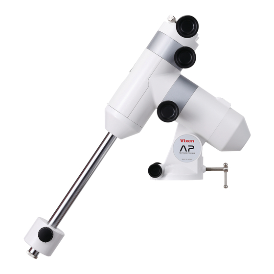
BEFORE USE Name of Each Component: AP Photo Guider Equatorial Platform AP Mount Head Unit R.A Motor Module R.A Axis (Polar Axis) R.A. Clamp Lever 1/4” Camera Mounting Screw (4 points) Dovetail Slide Bar PG Safety Screw Polar Axis Cap (for Polar Scope) -
Page 8: Mount & Cotroller Specifications
USB Micro-B (DC4.4 to 5.26V) Power Supply Por t USB Ex ternal batter y pack (Not sold by Vixen) Power Supply About 4 hours (at 20 degree C, with Alkaline batteries, 6kg loading weight ), 2.5 hours if the DEC Working Duration with motor module is used together. -
Page 9: Check The Package Contest
Note 1: The contents of your AP-SM mount package may differ when you purchase it as a complete AP-SM telescope package. Note 2: The AP-SM packages do not contain an adapter for power supply. Use 4 x AA batteries (not included) or a commercially available USB external battery with USB Micro-B adapter. - Page 10 Spiked Feet T h e AP- SM M o un t Pa c k a g e w i t h A 8 0 M f O p t i c a l Tub e a n d APP-T L13 0 Tr ip o d a r e s h o w n a s a n ex a mp l e.
-
Page 11: Ap-Sm Mount
USB Micro-B (DC4.4 to 5.26V) Power Supply Por t 4 x AA batteries (Alkaline or Ni-MH, Ni-Cd rechargeable batteries), External USB battery pack (Not sold by Vixen) Power Supply About 4 hour s (at 20 degree C, with Alkaline bat teries, 6kg loading weight ), 2.5 hour s if the Working Duration with DEC motor module is used together. - Page 12 Counterweight bar Counterweight bar Right Ascension (R.A.) If the AP mount is set to be aligned with one rotational a xis parallel to the Ear th’s a xis, the motion of R.A will follow the motion of stars. North North...
- Page 13 Power Supply Port T he AP- SM m ount r uns on s elf- c ont aine d four (4) A A – size ba t ter- ies, or a USB ex ter nal ba t ter y. T he USB ex ter nal ba t tey with USB...
-
Page 14: Star Book One Components Guide
BEFORE USE STAR BOOK ONE Components Guide Note: Usage of the STAR BOOK ONE is described as operating instructions for the AP-SM Mount here. ( 10 ) Eyelet ( 10 ) Star Patent Pending DC12V Max.0.5A LCD Monitor x999 ( 4 ) RA Reverse button... -
Page 15: Preparation Assembling The Mount
PREPARATION Assembling the Mount Refer to the instruction manual of your telescope and accessory together with this manual when you attach the optical tube assembly to the mount. The unit includes heavy items. Take care not to drop them when assembling as it could cause seriously damage the equipment or lead to injury. Take care not to pinch your finger with moveable pieces when setting up. - Page 16 PREPARATION A t t a c h t h e m e t a l p o s t o n t h e t r i p o d h e a d . T h e m e t a l p o s t i s u n d e r n e a t h t h e c e n t e r c o l u m n .
- Page 17 .
-
Page 18: Attaching The Counterweight
PREPARATION Attaching the Counterweight Be sur e to a t t ach the counte r we ight b e for e you ins t all the op tic al tub e asse mbly on the mount . S c r e w t h e c o un t e r w e i gh t b a r in t o t h e v a n i t y r i n g un t il i t i s s n u g. T hen, tur n it ba c k by one r oation. -
Page 19: Attaching The Optical Tube Assembly
PREPARATION Attaching the Optical Tube Assembly The telerscope tube attaches to the AP mount via a dovetail tube plate. The permissible loading weight of the mount is 6kg (13.2 lbs). Dovet a il tub e pla te D ovet a il Sli de bar Caution: Take c ar e not to drop the te le scop e tub e as it could r e sult in se rious damage . -
Page 20: Attaching The Dovetail Slide Bar (Ap Photo Guider)
PREPARATION Attaching the Dovetail Slide Bar AP Photo Guider Loosen both the dovetail plate lock screw and safety screw on the mount head fully so that space is available for the dovetail slide bar. D ovet a il pla te... -
Page 21: Balancing The Equatorial Mount
T he Vi xen AP is a German e quator ial mount, in whic h the r ot ating R. - Page 22 PREPARATION Second Step: Balancing the Mount in Declination (DEC) This should be doen af ter you finish balancing in the R.A. In case of a telescope tube with tube rings: While holding the telescope tube, turn the counter weight bar (or telescope tube) by hand until the counter weight bar is horizontal.
- Page 23 PREPARATION Using a telescope tube with dovetail slide bar: This should be done af ter you finish balancing in the R.A. While holding the telescope tube, turn the counter weight bar (or telescope tube) by hand until the counter weight bar is horizontal. The declination body keeps the mount in position.
- Page 24 PREPARATION Tips on Proper Balancing The balanc e arr angement s b elow illus trate var ious p os sible s et tings dep endent on the length and weight of your optic al tub e. The c enter of gravit y of the teles c op e is gi ven a s 25 c m (10 ” ) fr om the inter s e c tion of the R. A and DEC a xes. Guidance 2...
-
Page 25: Connecting The Star Book One
Connecting the STAR BOOK ONE The AP-SM mount package comes equipped with an RA motor module and STAR BOOK ONE controller as standard accessories. Plug one end of the STAR BO OK c a ble into the c onne c tion p or t on the mount. -
Page 26: About Power Supply
PREPARATION About Power Supply The AP-SM mount runs on self-contained four (4) A A – size batteries, or a USB external batter y. The AC Adapter 12V-3A for SX mount is not available for the AP-SM mount. Installing AA-size Batteries The A A –... - Page 27 PREPARATION Using a USB External Power Supply Us e a c ommer c ially availa ble USB ex ter nal bat ter y with USB Mic r o - B c onne c tor. N o t e 1: T h e U S B e x t e r n a l b a t t e r y w i l l t a k e p r i o r i t y o v e r t h e A A b a t t e r i e s i f y o u t u r n o n t h e p o w e r w h i l e t h e A A bat ter ies remain in the bat ter y c ompar tment.
-
Page 28: Initial Setting And Basic Operation : Tuning On The Power
Turning ON the Power The power switch is located on the bottom of the R.A motor module if you have the AP-SM mount version. To turn on the power, press the side marked “I “on the switch, and to turn off the power, press the “O”... -
Page 29: Moving The Ap Mount
Moving the AP Mount The AP M ount is designe d to move and s top the r ot ational a xes without a c lamp sys tem. The trac k ing and slow motion c ontr ol are done with the manual slow motion c ontr ol k nobs. -
Page 30: Changing Tension Of The Friction Stop Motion
INITIAL SETTING AND BASIC OPERATION Changing Tension of the Friction Stop Motion The tension of the fr ic tion s top motion c an b e a d jus te d in the R. A and DEC a xes a s the nee d ar is es. The p osition of ea c h tension a d jus tment s cr ew for the R. -
Page 31: Approximate Polar Aligning With The Finder Scope
A f ter s et ting up the teles c op e, lo c ate the AP mount s o that it s R. A a xis p oint s towar d the nor th c eles tial p ole. - Page 32 INITIAL SETTING AND BASIC OPERATION Find Polaris from Cassiopeia and the Big Dipper A rough set ting with a compass or pointing the polar a xis of your telescope’s mount at Polaris will work well for visual obser vation. The constellations Cassiopeia and the Big Dipper (par t of Ursa Major) are near Polaris. You will be able to find Polaris if you know the position of these groups of stars.
-
Page 33: Approximate Polar Aligning With The Polar Meter
Cha n g e t h e dir e c t i o n o f t h e AP m o un t s o t ha t t h e p o in t er o n t... -
Page 34: Application Polar Alignment Scope
APPLICATION Polar Alignment Scope If your intent i on is t o t a ke l on g ex p osur e a s tr oph ot o gr a phy, you mus t a c c ur a tel y ali gn the p olar a x is (R. A) of the m ount t o the celestial pole. - Page 35 APPLICATION Replacing the Battery While holding the brightness adjusting dial by hand, remove the bat ter y cover Battery cover Battery cover (the power switch for illuminator) on the top of the brightness adjusting dial by turning it counterclock wise. Turn the bat ter y c ompar tment on the p o la r a li gnm en t s c o p e d o w n wa r d a s s h o w n i n t h e f i g u r e s o t h a t t h e o l d...
-
Page 36: Polar Alignment In The Northern Hemisphere
Polar Alignment in the Northern Hemisphere The polar a xis of the AP equatorial mount is aligned to the Nor th Celestial Pole in the nor thern hemisphere. The polar alignment scope utilizes 3 stars of Polaris, Delta UMi and 51 Cep near the Nor th Pole. Positions of the above stars are plot ted on the reticle of the polar alignment sc ope. - Page 37 APPLICATION Open the round window on the declination body by sliding down the shut ter of the window. While looking into the polar alignment scope, turn the polar alignment scope body so that the engraved Big Dipper (or Cassiopeia) on the reticle matches the Big Dipper (or Cassiopeia) in the real sk y.
- Page 38 APPLICATION While looking into the eyepiece of the C eles t ial n or t h C eles t ial n or t h C eles t ia l n or t h C eles t ia l n or t h polar alignment sc ope, adjust...
- Page 39 Since there is no mark that points at the Nor th Celestial Turn the polar alignment scope body so that Delta UMi Pole, you need to match the polar a xis of your AP comes near to the location of the year 2014 on the scale.
- Page 40 APPLICATION While looking into the eyepiece of the C eles t ial n or t h C eles t ial n or t h C eles t ia l n or t h C eles t ia l n or t h polar alignment scope, turn the altitude adjustment bolt and azimuth adjustment knobs so that Polaris comes to the gap...
-
Page 41: Polar Alignment In The Southern Hemisphere
Polar Alignment in the Southern Hemisphere The polar a xis of the AP equatorial mount is aligned to the South Celestial Pole in the southern hemisphere. The polar alignment scope utilizes 3 stars of Sigma Octantis, Tau Octantis and Chi Octantis near the South Pole. Positions of these star are plot ted on the reticle of the polar alignment s c ope. - Page 42 APPLICATION Open the round window on the declination body by sliding down the shut ter of the window. While looking into the polar alignment scope, turn the polar alignment scope body so that the engraved Southern Cross (or Alpha Eridani) on the reticle directs the Southern Cross (or Alpha Eridani) in the real sk y.
- Page 43 APPLICATION While looking into the eyepiece of the C eles t ia l s out h C eles t ia l s out h C eles t ia l s out h C eles t ia l s out h polar alignment scope,...
- Page 44 Since there is no mark that points at the South Celestial Pole, Turn the polar alignment scope body so that Tau Octantis you need to match the polar axis of your AP equatorial mount comes near to the location of the year 2014 on the scale.
- Page 45 APPLICATION While looking into the eyepiece of the C eles t ia l s out h C eles t ia l s out h C eles t ia l s out h C eles t ia l s out h polar alignment scope, turn the altitude adjustment bolt and azimuth adjustment knobs so that Sigma Octantis comes to...
- Page 46 APPLICATION Tips on Finding Octans The constellation Octans is made up of dark stars about 5th magnitude on average. The nearest star to the south celestial pole is Sigma Oc tantis, which is one of four stars forming a trapezoid in Oc tans, visible at 5.5th magnitude. There are a few methods to locate inconspicuous Octans using the surrounding stars.
-
Page 47: Mount Menu
APPLICATION Change Settings on the Mount / Controller STAR BOOK ONE controller menus allow you to change your desired settings on the mount (and controller) Mount Menu Pr es sing the MOUNT but ton will tur n up the br ightnes s of the but ton it s elf an d all ow you to a c c es s var ious M ount menus using the dir e c tion key s. -
Page 48: Tracking Direction
Display the “TrackDir N Hemis” to choose the tracking direction setting. For the use of the AP mount in the southern hemisphere, you need to revise the rotation of the motor. Display the “TrackDir S Hemis” with the up or down direction key to choose. -
Page 49: Backlash Compensation
APPLICATION Backlash Compensation B a c k la sh is a m oment ar y s top pa ge of the tr a c k ing m otion of the m ount that o c c ur s when the m otor gear s r ever s e their r ot ation. B a c k la s h d o es not o c c ur while the m ount c ontinues tr a c k ing a t a c ons t ant s p ee d a s the gear s keep c ont a c t with ea c h other, however, it may o c c ur when the teles c op e is slewe d with dif fer ent s p ee ds. - Page 50 APPLICATION Press the Mount button to make the direction keys available. Confirm the amount of backlash in the direction of RA. Center the star in the field of view of your eyepiece and watch how the star moves while pressing the left direction key. Keep pressing the direction key until the star begins to move.
-
Page 51: Setting For Autoguider
APPLICATION Setting for Autoguider T he STAR B O OK ONE c an b e us e d for auto gui ding in c on junc tion with an ex ter nal auto gui ding sys tem that is c ompatible with the SBIG auto gui der. -
Page 52: Pec
(e.g. 6 0 0 s e c on ds with the AP m ount) in the dir e c ti on of R. A . T his is c aus e d by the m otion of the tr a c k ing gear wheels an d it is par t of the desi gn of e qua tor ial m ount s. - Page 53 APPLICATION Stopping the PEC Recording Press the MOUNT or DISPLAY button to stop the PEC recording. The dialogue “PEC StopRec” appears on the display and press the + button to stop. Pressing the minus button will cancel the StopRec? dialogue and continue the PEC recording. If the PEC recording is stopped, only the ongoing record of the current cycle is cleared.
-
Page 54: Display Menu
APPLICATION Display Menu Pr es sing the DISP. but ton will tur n up the br ightnes s of the but ton it s elf an d all ows you to a c c es s var ious Dis play menus for s et ting with the dir e c ti on key s. At the s ame time, it dis a bles the dir e c tion key s for slewing the m ount. -
Page 55: Red Led Light Adjustment
Press the DEC Reverse button again to return the tracking to the original direction. Reset All the settings for the mount and controller can be initialized to the defaulted settings at the Vixen Reset factory. To reset the settings, turn on the power while pressing the plus button and the red LED light Memory button simultaneously for more than one second. -
Page 56: Ap Mount Composition Chart
APPLICATION Modules for the AP Mount The AP mount is composed of sectional modules and units. It can be easily rearranged or upgraded for your specific need. AP Mount Composition Chart AP Clamp Lever Manual Slow Motion AP Clamp Mount Head Unit... -
Page 57: Variations On The Ap Mount
(w/ Mount Base) AP Declination Body Unit Counterweight Bar Unit R.A Motor Module (w/ STAR BOOK ONE) AP Polar Axis Body Unit (w/ Mount Base) AP Mount with Dual-Axis Motor Drive DEC Motor Module Consisting of: AP Clamp Mount Head Unit AP Clamp Mount Head Unit R.A Motor Module... -
Page 58: How To Change The Modules
APPLICATION How to Change the Modules Remove the optical tube, counter weight bar and controller before changing modules. Take out the bat teries from the bat ter y compar tment and disconnect the ex ternal power supply if it is used. Case 1: Changing the R.A. -
Page 59: Slow Motion Control Module
APPLICATION Turn the manual slow motion control module so that the Manual slow motion Manual slow motion control module control module screw holes (larger holes with no thread) are aligned in tandem. Replace the three socket head cap screws in place. -
Page 60: Changing The Manual Slow Motion Control Module For The Dec. Motor Module
APPLICATION Case 2: Changing the Manual Slow Motion Control Module for the DEC. Motor Module. Remove the declination body cover. Declination body cover Declination body cover Open up the polar scope window on the declination body by sliding down the shut ter. While pushing down on the hook on the bot tom of the declination body, pull out the declination body cover by pinching the hook and window Window... - Page 61 APPLICATION At tach the declination body assembly onto the polar a xis body assembly so that the DEC motor module DEC motor module electrical contact on the declination body fits snugly on the sunken por tion on the manual slow motion control unit as shown in the figure. Electrical contact Electrical contact Replace the t wo socket head cap screws that were removed in step 3 above while...
- Page 62 APPLICATION Case 3: Changing the Maunal Slow Motion Control Module for the R.A. Motor Module Remove the declination body cover. Declination body cover Declination body cover Open up the polar scope window on the declination body by sliding down the shut ter. While pushing down on the hook on the bot tom of the declination body, pull out the Window Window...
- Page 63 APPLICATION Turn the R.A motor module to change the orientation so that R.A motor module R.A motor module the screw holes (larger holes with no thread) are aligned in Allen wrench Allen wrench tandem. Replace the the three socket head cap screws in place and tighten the screws securely with the 3mm Allen wrench.
-
Page 64: Upgrading The Ap Photo Guider To The Ap Mount
APPLICATION Upgrading the AP Photo Guider to the AP Mount with Dual-axis Motor Drive Ne cessar y Par ts (Optional) · AP Clamp Mount Head Unit 4mm Allen wrench 4mm Allen wrench · DEC Motor Module · AP Declination Body Unit... - Page 65 4mm Allen wrench 4mm Allen wrench using the 4mm Allen wrench. At tach the AP clamp mount head unit onto the DEC motor Mount head unit Mount head unit module with the electrical contact on the outside so that the...
- Page 66 APPLICATION While holding the DEC motor module, fix the declination body securely with the t wo supplied M5-25mm long screws using the 4mm Allen wrench. Install the bat teries, if necessar y. 4mm Allen wrench 4mm Allen wrench Replace the declination body cover with at tention to the direction of the hook on the cover.
-
Page 67: Replacing The Fuse
APPLICATION About a Fuse Box In the AP mount, the electrical circuit board is protected by a Specifications: fuse. It is a rare case that a fuse is cut of f in general use of 125V 1A Class-B (PES standard) the mount. -
Page 68: Specifications
SPECIFICATIONS Connectors on the STAR BOOK ONE Patent Pending DC12V Max.0.5A 6 5 m m( 2 . 5 6 ” ) C on t rol l er cabl e con n e ct in g p o r t ( D -S U B 9 P I N ma l e p l u g ) A ut o g ui der port Ra−... -
Page 69: Dimensions
SPECIFICATIONS AP Mount Dimensions 2 7 4 m m( 1 0 . 7 8 ” ) 79mm ( 3.11”) 80mm( 3.15”) Fulcrum φ96mm(3.78”) φ 44 . 8m m 112mm(4.41”) ( 1 . 7 6 ” ) R.A Motor Module Dimensions DEC Motor Module Dimensions φ... - Page 70 SPECIFICATIONS Manual Slow Motion Control Module Dimensions Wo r m g e a r sh a ft 3 8 . 5 m m ( 1. 52”) φ78mm( 3.07”) φ7 8 m m (3 . 0 7” ) APP-TL130 Tripod Dimensions...
- Page 71 M e m o...
- Page 72 5-17-3 H igash itokorozawa,Tokorozawa, Sai tama 359-0021, Japan P h o n e +81-4-2944-4141 ( International ) ht t p s:/ / w w w.vixen.c o. jp F a x +81-4-2944-9722 ( International ) 67キ-12-(80000337)-0.5S- -(Miz)(K )(M)
Need help?
Do you have a question about the AP and is the answer not in the manual?
Questions and answers