Advertisement
Quick Links
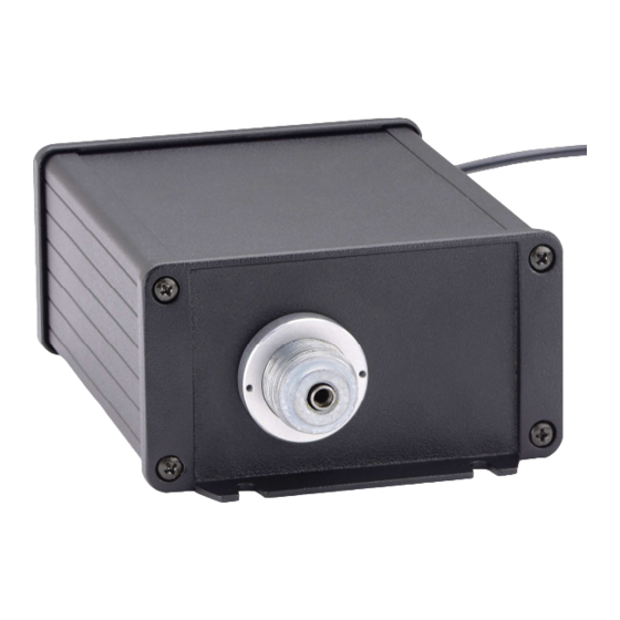
The Dakota Digital ECD-100 is designed operate a cable-driven speedometer from a
transmission or ECM electric speed signal. Cables are available for GM thread-on (5/8" thread), GM
clip-on, or Ford clip-on. The supplied cable threads on to one end of the ECD-100 and the wiring
harness exits on the other end. Do not use the vehicle's original speedometer cable; use the one
supplied with the ECD-100. The module is fully sealed and can be mounted under the dash or in the
engine compartment. The module should not be mounted under the vehicle due to the danger of
road debris causing damage. The unit is fully adjustable from the comfort of your driver's seat.
GM 5/8" thread
ECD-100 wiring connections:
RED – 12V power with key on.
BLACK – Ground.
WHITE – Vehicle speed signal.
GREEN – Input for setup switch. (grounding to activate)
For 2-wire transmission speed sensors that are not connected to anything else, the polarity of
the wires does not matter. Connect one wire to the WHITE wire on the ECD-100 and the other to the
same ground point as the BLACK wire on the ECD-100. Twisting the ground and signal wires around
each other provides an additional level of interference protection. The speed signal wire should not
be routed alongside tach, ignition, or other high current or high voltage wires.
For vehicles which have a vehicle speed signal from a transmission controller or ECM, tap into
the VSS wire and connect it to the WHITE wire on the ECD-100. Consult a vehicle service manual or
wiring diagram to determine wire color and location.
ECD-100
ELECTRONIC CABLE DRIVE
GM clip-on
Ford clip-on
1
MAN# 650445:C
Advertisement

Related Manuals for Dakota Digital ECD-100


Summary of Contents for Dakota Digital ECD-100
- Page 1 For 2-wire transmission speed sensors that are not connected to anything else, the polarity of the wires does not matter. Connect one wire to the WHITE wire on the ECD-100 and the other to the same ground point as the BLACK wire on the ECD-100. Twisting the ground and signal wires around each other provides an additional level of interference protection.
- Page 2 The switch should be mounted in the car, with easy driver access. The LED’s on the ECD-100 will indicate the setup mode, and the ECD-100 will also move the speedometer needle to different positions during the setup, without having to see the control unit.
- Page 3 GREEN and RED lights off. on the ECD-100. It should be 11-15 V dc. Speedometer will not work. ECD-100 is in setup mode. The green wire should be disconnected RED light on steady. Green wire is grounded. for normal operation.
- Page 4 24 months from date of original purchase. No person or representative is authorized to assume, for Dakota Digital, any liability other than expressed herein in connection with the sale of this product.