Table of Contents
Advertisement
Quick Links
Advertisement
Table of Contents

Related Manuals for RTimes RTSO-9001


Summary of Contents for RTimes RTSO-9001
- Page 1 RTSO-9001 Reference manual Realtimes Beijing Technology Co., LTD. Fax:+86 010-84284669 / 84280996 Email: info@realtimes.cn Web Page: https://www.realtimesai.com Address: 11th Floor, Block B, 20th Heping Xiyuan, Pingxi Street, Chaoyang District, Beijing 100013,P.R.China...
- Page 2 V1.2 2018-05 Fixed serial port function V1.0~V1.2 V1.2.1 2018-06 Updated layout and graphics V1.0~V1.2.1 V1.2..2 2018-07 Change Recovery Part Description V1.0~V1.2.1 V2.0 2019-03 Manual style template update V1.0~V1.2.1 V3.0 2020-06 Add notes and lights V1.0~V1.2.1 Manual for RTSO-9001 V2.0...
- Page 3 Therefore, it is recommended to observe anti-static safety precautions when handling any circuit board component (including RTSO-9001). Anti-static safety protection measures include, but are not limited to the following: a) The smart box should be placed in an anti-static bag during transportation and storage, and then the board should not be taken out during installation and deployment.
- Page 4 3) Burn in verification of all BSP support packages provided by the company; 4) The company released burn environment construction, entry-level use. ; 5) Various peripheral module drivers released by the company; 6) The company's product fault diagnosis and after-sales maintenance services; Manual for RTSO-9001 V2.0...
- Page 5 Updates of subsequent documents, BSP, driver files and other official account will be updated in time. We will pay close attention to our developments in order to ensure that your information is up to date. We will push through WeChat public. Manual for RTSO-9001 V2.0...
-
Page 6: Table Of Contents
ATTERY INTERFACE 4.17 R (J12)........................30 ECOVERY JUMPER WIRE 5 MIPI Schematic design of camera interface section....................30 6 HARDWARE UPDATE HISTORY..........................35 7 PRODUCT SIZE................................35 8 SOFTWARE/BSP DETAILS............................36 REALTIMES BEIJING TECHNOLOGY CO.,LTD....................36 TERMS OF WARRANTY..............................36 Manual for RTSO-9001 V2.0... -
Page 7: Product Introduction
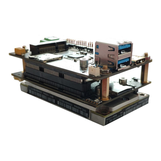
1 Product introduction Rtso-9001 is a low-cost, small-volume board with the NVIDIA® Jetson™ TX2 core module. The board consists of two board CARDS, RTSO-9001T and RTSO-9001B, both on the upper and lower stack. The length and width of the board are comparable to the NVIDIA Jetson® TX2 module and are suitable for compact deployment requirements. -
Page 8: Ordering Information
MIPI CSI-2(6 ways expandable), 4 x GPIO, 1 x miniPCIe, 1 x mSATA, 2 x RS-232/422/485, 1 x microSD, 1 x microSIM, 1 xAudio,RoHS Compliant,To provide ruitai new Era RTSO-9001 Linux4Tegra software support package. RTSO-9001-Cable RTSO-9001 Interface package (optional) Mini-pcie Video Capture Card... -
Page 9: Cable Kits And Accessories
Realtimes Beijing Technology Co.,LTD www.realtimesai.com Cable kits and Accessories Rtso-9001 supporting wire package order model is: RTSO-9001-Cable.Contains the following components: Subassembly Quantity Functional Description GPIO and Function Convert the on-board needle discharge interface to the wire discharge Button Line outlet... -
Page 10: Connector Locations
Realtimes Beijing Technology Co.,LTD www.realtimesai.com Connector Locations RTSO-9001T(The Upper Plate)Front RTSO-9001T(The Upper Plate)Back Manual for RTSO-9001 V2.0... - Page 11 Realtimes Beijing Technology Co.,LTD www.realtimesai.com RTSO-9001B(The Lower Plate)Front RTSO-9001B(The Lower Plate)Back Manual for RTSO-9001 V2.0...
-
Page 12: Function Connector
Ethernet connection status indicator Lighting Form-Network startup Network data rate indicator light Flicker-Data transmission Ethernet connection status indicator Lighting Form-Network startup 3.3V power light Lighting Form-power on The board level RTSO-9001B(The Lower Plate) Mandatory Sign Functional Description Status description Manual for RTSO-9001 V2.0... -
Page 13: Key And Dial Code Switch
USB cable to link the keyboard and mouse...) Connect the power cord to the power supply. RTSO-9001 adopts the automatic power on design, turns on the power and the system starts to work. For the system without protective enclosure, please avoid moving the whole system after the system is powered on. -
Page 14: Recovery Mode
The steps to enter the Recovery mode are as follows: Power down the device. Use USB cables to connect the lower USB port of RTSO-9001's double LAYER USB port (U4) to the Jetson development host USB port. Stub 1 pin (FRC) and 2 pin (GND) to J12 Force Recovery interface. -
Page 15: Connectors Description
Pin define core module data book. 4.2 FAN interface(J6) Function Connect external cooling fan The board RTSO-9001B(The lower plate) level Marking Molex PicoBlade Header Type Pin define Signal Signal TACH Pin-1:The Green box on the right. Manual for RTSO-9001 V2.0... -
Page 16: Micro Sim Card Slot(U3
UIM_CLK UIM_VPP UIM_DATA 4.4 Micro SD card slot(U5) Micro SD(TF)card slot Function RTSO-9001B(The lower plate) The board level Marking Type Micro SD(TF) Pin define 引脚 信号 引脚 信号 SDIO_DATA2 SDIO_DATA3 SDIO_CMD SDIO_VCC SDIO_CLK SDIO_DATA0 SDIO_DATA1 SDIO_CD Manual for RTSO-9001 V2.0... -
Page 17: Power Connector(J2
TMDS Data2 GND TMDS Data2+ TMDS Data2- TMDS Data1 GND TMDS Data1+ TMDS Data1- TMDS Data0 GND TMDS Data0+ TMDS Data0- TMDS Clock GND TMDS Clock+ TMDS Clock- DDC clock DDC data +5V Power Hot Plug Dete Manual for RTSO-9001 V2.0... -
Page 18: Ethernet Interface(J8,J9
2.0mm ,2x5 Pin Double row pins Pin define Signal Signal MDI1+ MDI1- MDI2+ MDI2- MDI0+ MDI0- MDI3+ MDI3- Pin-1:The green box on the right. Pin-2:The red box on the right. J9 is the core module native network port. Manual for RTSO-9001 V2.0... -
Page 19: Usb3.0(U4
OTG interface location: green box logo on the right. The lower USB2.0 port of the connector works in OTG mode for system burning. When RTSO-9001 is used with Jetson TX2, if mini-PCIe is enabled, the upper USB3.0 port of the connector will not be available. -
Page 20: Mini-Pcie Interface(U2
SMB_CLK PCIE_TX- SMB_DAT PCIE_TX+ CON_USB2_D- CON_USB2_D+ VCC_3V3_PCIE VCC_3V3_PCIE 1.5V 3.3V When rtSO-9001 is used with Jetson TX2, if mini-PCIe is enabled, the upper LAYER of the U4 double-layer USB connector USB3.0 port will not be available. Manual for RTSO-9001 V2.0... -
Page 21: Audio And Can Interface(J10
RTSO-9001T(The upper plate) level Marking Type 2.0mm ,2x5Pin Double row pins Pin define Signal Signal MIC_IN CAN0_H AUDIO_GND CAN0__L AUDIO_HR_R AUDIO_GND CAN1_H AUDIO_HR_L CAN1_L Pin-1:The green box on the right. Pin-2:The red box on the right. Manual for RTSO-9001 V2.0... -
Page 22: Mipi Interface (J1,J4,J5
Type Dai-ichi Seiko:I-PEX30-0.4mm 20525-030E-02 Pin define 管脚 信号 管脚 信号 VDD3V3 VDD3V3 VDD3V3 VDD5V CSI3_CLK_N CSI3_CLK_P CAM_P1_CLKA CAM1_RST# CAM2_SDA CAM2_SCL CSI3_D0_N CSI3_D0_P CSI2_D0_N CSI2_D0_P CSI2_CLK_N CSI2_CLK_P CSI2_D1_P CSI2_D1_N CSI3_D1_N CSI3_D1_P Pin-1:The green box on the right. Manual for RTSO-9001 V2.0... - Page 23 Marking Type Dai-ichi Seiko:I-PEX30-0.4mm 20525-030E-02 Pin define Signal Signal VDD3V3 VDD3V3 VDD3V3 VDD5V CSI1_CLK_N CSI1_CLK_P CAM_P0_CLKA CAM0_RST# CAM0_SDA CAM0_SCL CSI1_D0_N CSI1_D0_p CSI0_D0_N CSI0_D0_P CSI0_CLK_N CSI0_CLK_P CSI0_D1_N CSI0_D1_P CSI1_D1_N CSI1_D1_P Pin-1:The green box on the right. Manual for RTSO-9001 V2.0...
- Page 24 Marking Type Dai-ichi Seiko:I-PEX30-0.4mm 20525-030E-02 Pin define Signal Signal VDD3V3 VDD3V3 VDD3V3 VDD5V CSI5_CLK_N CSI5_CLK_P CAM_P2_CLKA CAM2_RST# CAM2_SDA CAM2_SCL CSI5_D0_N CSI5_D0_p CSI4_D0_N CSI4_D0_P CSI4_CLK_N CSI4_CLK_P CSI4_D1_N CSI4_D1_P CSI5_D1_N CSI5_D1_P Pin-1:The green box on the right. Manual for RTSO-9001 V2.0...
-
Page 25: Msata Interface(U4
4.12 mSATA interface(U4) Function mSATA connector The board RTSO-9001B(The lower plate) level Marking Type 6.7mm high, full-length mSATA slot Pin define Signal Signal 3.3V 1.5V SATA TX+ 3.3V SATA TX- SATA RX- SATA RX+ 3.3V 3.3V 3.3V Manual for RTSO-9001 V2.0... -
Page 26: Dip Switch Interface(Sw2
Serial port 1 sends matching resistors For serial port function options, see serial port details (4.14 serial port). USB OTG enabled: it needs to be turned on when burning the system. (ID line ON is grounded, OFF is suspended) Manual for RTSO-9001 V2.0... - Page 27 Mode ON/OFF ON/OFF BIT8 ON opens the sender to match the resistance The mapping files of serial port 0 and serial port 1 in Linux system are ttyS0 and ttyTHS2 in /dev directory respectively. Manual for RTSO-9001 V2.0...
-
Page 28: Serial Port(J4
RTSO-9001T(The upper plate) level Marking Type 2.0mm ,2x5Pin Double row pins RTSO-9001 provides two RS232/RS422/RS485 serial communication Descriptio interfaces. Users can use BIT1, BIT2 and BIT3 on the dial code switch SW2 to select the mode. Pin define Mode 0... - Page 29 RTSO-9001T(The upper plate) level Marking Type 2.0mm ,2x5Pin Double row pins Rtso-9001 provides two RS232/RS422/RS485 serial communication Descriptio interfaces. Users can use BIT1, BIT2 and BIT3 on the dial code switch SW2 to select the mode. Pin define Mode3 232 can only receive data...
- Page 30 RTSO-9001T(The upper plate) level Marking Type 2.0mm ,2x5Pin Double row pins RTSO-9001 provides two RS232/RS422/RS485 serial communication Descriptio interfaces. Users can use BIT1, BIT2 and BIT3 on the dial code switch SW2 to select the mode. Pin define Mode6 232 one way, 422 one way...
-
Page 31: Gpio And Button Interface(J5
The SYSFS mapping Numbers in the TX2 system are: 486,480,298,388. 4.16 RTC Battery interface(ID1) Function Battery Pin The board RTSO-9001T(The upper plate) level Marking Type 1.0mm spacing 1x3Pin single row straight needle insertion Pin define Signal Signal Pin-1:The green box on the right. Manual for RTSO-9001 V2.0... -
Page 32: Recovery Jumper Wire(J12
Schematic design of camera interface section For customers developing MIPI interface cameras that can be adapted to rtSO-9001 boards, please refer to part of the schematic design of the MIPI interface section of RTSO-9001 below for hardware adaptation design. Manual for RTSO-9001 V2.0... - Page 33 Realtimes Beijing Technology Co.,LTD www.realtimesai.com MIP Interface CAMn_CLKn design schematic MIPI interface IIC extension design schematic Manual for RTSO-9001 V2.0...
- Page 34 Realtimes Beijing Technology Co.,LTD www.realtimesai.com MIPI interface design schematic Manual for RTSO-9001 V2.0...
- Page 35 Realtimes Beijing Technology Co.,LTD www.realtimesai.com MIPII interface design schematic Manual for RTSO-9001 V2.0...
- Page 36 Realtimes Beijing Technology Co.,LTD www.realtimesai.com MIPI I interface design schematic Manual for RTSO-9001 V2.0...
-
Page 37: Hardware Update History
Realtimes Beijing Technology Co.,LTD www.realtimesai.com 6 Hardware update history RTSO-9001 Board hardware update history edition Updata description V1.0 Initial release V1.1 Modify the power circuit, modify part of the device package, modify the serial port connection V1.2 Add power input overvoltage protection, fix PCIE part problem V1.2.1... -
Page 38: Software/Bsp Details
8 Software/BSP Details RTSO-9001 boards work on systems that are burned using the official original NVIDIA Linux For Tegra (L4T). HDMI, own Gigabit Ethernet, extend Gigabit Ethernet, double layer USB interface upper interface 2.0, 3.0 several lower interface 2.0, serial port, GPIO, SD card, mSata, fan interface, CAN be supported. However, mini-PCIe, the lower interface of double-layer USB interface USB3.0, MIPI camera interface, cannot work... - Page 39 Rev.C 6/2020 Manual for RTSO-9001 V2.0...
Need help?
Do you have a question about the RTSO-9001 and is the answer not in the manual?
Questions and answers