Advertisement
Quick Links
Advertisement

Related Manuals for Inspire FPC1

Summary of Contents for Inspire FPC1
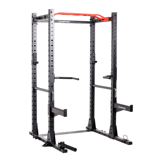
- Page 1 FPC1 FULL POWER CAGE PAGE 1...
- Page 2 WARRANTY / DISCLAIMER BEFORE YOU BEGIN Thank you for selecting the INSPIRE FPC1 RACK. For your safety and benefit, read this manual carefully before using the machine. As a manufacturer, we are committed to providing you complete customer satisfaction. If you have any questions, or find there are missing or damaged parts, please call our TOLL-FREE customer service number.
- Page 3 IMPORTANT SAFETY NOTICE Precautions This exercise machine is built for optimum safety. However, certain precautions apply whenever you operate a piece of exercise equipment. Be sure to read the entire manual before you assemble or operate your machine. Please note the following safety precautions: 1.
- Page 4 PAGE 4...
- Page 5 EXPLODED VIEW PAGE 5...
- Page 6 COMPONENTS LIST 7 X 1 16 X 4 X 10 PAGE 6...
- Page 7 COMPONENTS LIST 40 X 2 PAGE 7...
- Page 8 HARDWARE PACK PAGE 8...
- Page 9 STEP 1. BOTTOM SUPPORT FRAME ASSEMBLY Refer to the illustration above for location and orientation of components. This step consists of a left side and a right side. • Fasten with Bolt (28), Washer (36), and Locknut (35). Connect Bottom Foot Plate (15) to Bottom Base Frame (1), Bottom Inner Plate (13), and the Bottom Cross Brace (14), place these items towards the one end of the Bottom Base Frame.
- Page 10 STEP 2 Upright BeamS AND REAR CONNECTING FRAME INSTALLATION Refer to the illustration above for location and orientation of components. • Fasten with Bolt (28), at the bottom, Bolt (29) above, Washer (37), and Lock-Nut (35). Connect Upright Beam (5) to the Bottom Support Frame Assembly. Left side and Right side.
- Page 11 STEP 3 Upright Beams FRONT INSTALLATION Refer to the illustration above for location, and orientation of components. • Fasten with Bolt (29) at the bottom, Washer (36), and Lock-Nut (35). Connect Upright Beam (5) to the Bottom Support Frame Assembly. Left side and Right side. •...
- Page 12 Fix washer 37 #to STEP 4 UPPER CROSS BARS INSTALLATION Refer to the illustration above for location, and orientation of components. • Fasten with Bolt (29), Washer (37), Washer (36), and Lock-Nut (35). • Connect the Upper Cross Bar (2), to the 2 the Upright Beams. Left side and Right side.
- Page 13 STEP 5. Monkey Bar INSTALLATION. Refer to the illustration above for location, and orientation of components. • Fasten with Bolt (31), Washer (36), and Lock-Nut (35). • Connect the Monkey Bar (4), to the Upper Cross Bars (2), and Deco Plate (23).
- Page 14 STEP 6 RESISTANCE BAND PEGS, , LANDMINE, AND BATTLE ROPE ATTACHMENT INSTALLATION. Refer to the illustration above for location, and orientation of components. RESISTANCE BAND PEGS (4 Places): one at top, and one at bottom on each side. • Fasten with Bolt (30), Washer (36), and Lock-Nut (35). •...
- Page 15 STEP 7 HOOKS, PARALLEL BARS, AND SAFETY TUBES ATTACHMENT. Before beginning a workout, make sure all the safety tubes are in place. Locate a desired height to place the safety bar (12) thru the hole of the beam and the safety sleeve (40).
- Page 16 J-Cups (6), (7). Step 2 Step 1 Step 3 Parallel bars (10), (11) Step 2 Step 3 Step 1 Safety Catches (8), (9) Step 2 Step 1 Step 3 PAGE 16...
- Page 17 PAGE 17...
- Page 18 Labels Placement FPC1 FULL POWER CAGE PAGE 18...
- Page 19 PAGE 19...
Need help?
Do you have a question about the FPC1 and is the answer not in the manual?
Questions and answers