
Subscribe to Our Youtube Channel
Related Manuals for Palmgren 9681062


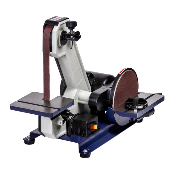
Summary of Contents for Palmgren 9681062
- Page 1 Operating Instructions & Parts Manual 1” x 42” Belt / 8” Disc Sander Model 9681062 9642804.01...
- Page 2 DAMAGE! RETAIN INSTRUCTIONS FOR FUTURE REFERENCE. PLEASE REFER TO BACK COVER FOR INFORMATION REGARDING PALMGREN'S WARRANTY AND OTHER IMPORTANT INFORMATION. Model #: ___________________ Serial #: ___________________ Purch. Date: _______________ © 2018 Palmgren / a C.H. Hanson Brand All Rights Reserved...
-
Page 3: Getting Started
SAFETY RULES For your own safety, read all of the Electrical requirements instructions and precautions before The power supply to the Model 9681062 Belt / Disc operating tool. Sander is 115V, 60Hz, 5.8 amps. The standard Always follow proper operating allowable voltage variation is a plus or minus 10%. -
Page 4: Electrical Connections
• Do not set up or use the Belt / Disc Sander in dangerous • Completely disconnect this machine from its power source environments. Do not set up or use the Belt / Disc Sander in when changing an abrasive disc or belt. damp or wet locations. -
Page 5: Extension Cords
SPECIFICATIONS 5. Do not abuse the cord. Never pull on a cord to unplug it from Model 9681062 - 8” Disc / 1” 42” Belt Sander an outlet. Keep the cord away from heat, oil, sharp edges Motor 1/3 HP, 120V, 60Hz, 5.8 amps... -
Page 6: Power Source
MODEL 9681062 BELT / DISC SANDER FUNCTIONAL PARTS A. Sanding Belt 1”x42” F ON/OFF Safety Switch K. Sanding Disc Table Lock P. Sanding Belt Dust Port Handle B. Sanding Belt Tracking G. Motor V-Belt Safety Q. Sanding Belt Platen Knob Cover L. -
Page 7: Assembling The Components
ASSEMBLING THE COMPONENTS The sander must no be plugged in and the power switch must be completely off until the assembly process has been correctly completed. Required tools The only tool needed for assembly that is not supplied is a #2 philips screwdriver. - Page 8 ASSEMBLING THE COMPONENTS - Install the dust port CONTINUED Install the inside belt guard Figure 8 18. Attach the Dust Port (#19) to the sanding disc base using the Figure 6 M6 Phillips head Screw and Washer (#18, 17) as shown in figure 8 above.
- Page 9 NOTE: It is easier to thread the bolt part of the handle locking adjustable handle through the bracket’s slot and into on first, then attach the handle to it using the spring the threaded hole of the sanding frame as shown in figure 13. loaded Allen head cap screw provided.
-
Page 10: Disc Sanding
3. There are two options for mounting the sander to the Disc sanding workbench: Dusty work environments may be hazardous to your health. Always wear a Use the two extra holes in the base (located by the front OSHA/NIOSH approved, properly fitting face mask or right foot, and rear left foot when looking at the sanding respirator. -
Page 11: Adjusting The Sanding Belt Tracking
4. Do not force the workpiece into the sanding disc. Sand using of the belt, and also helps to prevent burning of the sanded light pressure, letting the sanding abrasives time to do their surface from excessive abrasive-action heat build-up. work! 5. -
Page 12: Disc Table Adjustments
6. Center and press the new sanding disc firmly onto the disc OPERATION – CONTINUED plate. Adjusting the sanding belt tracking 7. Replace the sanding table and handle that were removed in step 2. Disc table adjustments Always ensure the sander is turned off and unplugged prior to making any Sanding adjustments to the machine. - Page 13 To get the full range of table angling, handle must be very loose, metal sanding disc plate, table assembly and lower disc so that it slides along the slot in the table bracket. The table can guard removed. then be moved back to get maximum angles. 1.
-
Page 14: Troubleshooting Guide
OPERATION – CONTINUED Miter gauge adjustments Always ensure the sander is turned off and unplugged prior to making any adjustments to the miter gauge. Lock knob Figure 25 A Miter Gauge is supplied with your sander, and can be used on the disc or belt tables, which have slots in their design to fit the miter gauge’s bar. - Page 15 TROUBLESHOOTING GUIDE Symptom Possible Cause(s) Corrective Action Motor stalls or runs slow - 1. Motor is overloaded. 1. Reduce the load on the motor. resulting in blown fuses or 2. Short circuit in the motor or loose 2. Inspect connections on motor for loose or shorted tripped circuit.
- Page 16 REPAIR PARTS ILLUSTRATION FOR MODEL 9681062 - BELT / DISC SANDER...
- Page 17 REPAIR PARTS LIST FOR MODEL 9681062 - BELT / DISC SANDER Ref. Ref. Description Part No. Qty. Description Part No. Qty. Carriage Bolt M10X20 Grommet 9642774.01 Flat Washer M10 Flat Key M5x50 Standard Spring Washer M10 Deep Groove Ball Bearing 6202 2RS 9642775.01...
-
Page 18: Maintenance
WIRING DIAGRAM - MODEL 9681062 BELT / DISC SANDER Capacitor Motor Black Black White Main Switch Green Green White Plug MAINTENANCE Always ensure the sander is turned off and unplugged prior to making any adjustments or maintenance to the machine. - Page 19 NOTES...
- Page 20 - 3 YEARS. The obligation of C.H. Hanson / Palmgren is limited solely to the repair or replacement, at our option, at its factory or authorized repair agent of any part that should prove inoperable.
Need help?
Do you have a question about the 9681062 and is the answer not in the manual?
Questions and answers