Table of Contents
Advertisement
Quick Links
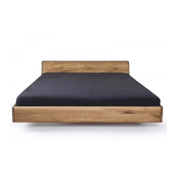
To assemble the bed you require
drill-driver, Philips screwdriver, 8mm hex key, rubber hammer, two adults.
Wooden elements:
Foot end (1) – 1 pc.
Head end (2) – 1 pc.
Head rest (3) – 1 pc.
Head rest end (4) – 1 pc.
Right side rail (5) – 1 pc.
Left side rail (6) – 1 pc.
Middle bar (7) – 1 pc.
Middle leg (8) – 1 pc.
Construction bar with legs (9) – 2 pcs.
Stabilising pins (10) – 20 pcs.
Stabilising bar (11) – 1 pc.
Head rest angle sill (12) – 1 pc.
Steel elements:
Maxifix cam (A) – 12 pcs.
Maxifix coupling (B) – 12 pcs.
Maxifix bolt (C) – 12 pcs.
Flat fitting (D) – 2 pcs.
"L" fitting (E) – 2 pcs.
"UT" fitting (G) – 4 pcs.
4 x 15 screw (short) – 14 pcs.
5 x 25 Spax screw (middle) – 24 pcs.
4 x 70 screw (long) – 4 pcs. (2 pcs.
are already mounted in the head
rest)
Allgemeiner Sicherheitshinweis:
Nicht mehr benötigte Verpackungsmaterialien und Kleinteile von Kindern fernhalten! Schwere Elemente nicht alleine heben!
ASSEMBLY MANUAL
LUGO BED
08/2013
Advertisement
Table of Contents

Related Manuals for mazzivo LUGO BED


Summary of Contents for mazzivo LUGO BED
- Page 1 ASSEMBLY MANUAL LUGO BED 08/2013 To assemble the bed you require drill-driver, Philips screwdriver, 8mm hex key, rubber hammer, two adults. Wooden elements: Foot end (1) – 1 pc. Head end (2) – 1 pc. Head rest (3) – 1 pc.
- Page 2 1. Step With the use of Spax 5x25 screws and a drill- driver secure the “UT” fittings (G) to the side rails (5 and 6) as per the marked holes (4 screws per one fitting). 2. Step With the use of 4x15 screws and the drill- driver secure the flat fitting (D) to the side rails (5 and 6) as per the marked holes.
- Page 3 7. Step Assemble all the frame elements together, so that they adjoin tightly. The stabilising bolts should fit in the holes, while the Maxifix bolts should fit in the cams. To facilitate this, the bed can be placed on the side rail. Remember to place the stabilising bar in the milled grooves in the head rest elements and head rest end.
- Page 4 11. Step Secure the “L” (E) fittings to the middle bar (7) with the use of a drill-driver and 4x15 screws. 12. Step Insert the middle leg (8) in the middle hole of the bar (7). 13. Step Place the middle bar (7) aligning the “L” fittings (E) with the flat fittings (D).
- Page 5 Produktinformationen | product information Stand: 07/2013 D - Allgemein Achten Sie bitte auf regelmäßige Lüftung der Räume. Zu trockene Luft fördert das Verziehen der Hölzer. Feuchtigkeit und Nässe sofort mit einem trockenen Tuch abwischen. Alle Oberflächen bitte nicht mit scharfen oder spitzen Gegenständen beschädigen. Oberflächen bitte nicht mit scharfen Putz- oder Reinigungsmitteln behandeln.
Need help?
Do you have a question about the LUGO BED and is the answer not in the manual?
Questions and answers