Table of Contents
Advertisement
Quick Links
Advertisement
Table of Contents
Troubleshooting

Related Manuals for Avid Technology VENUE S3L-X


Summary of Contents for Avid Technology VENUE S3L-X
- Page 1 VENUE | S3L-X System Guide and VENUE | Software 4.5...
- Page 2 Legal Notices © 2014 Avid Technology, Inc., (“Avid”), all rights reserved. This guide may not be duplicated in whole or in part without the written consent of Avid. 003, 192 Digital I/O, 192 I/O, 96 I/O, 96i I/O, Adrenaline, AirSpeed, ALEX,...
- Page 3 Safety Compliance Rack-Mount Safety Instructions 1) Elevated Operating Ambient - If installed in a closed or multi-unit rack Safety Statement assembly, the operating ambient temperature of the rack environment might be greater than room ambient. Therefore, consider installing the equipment in an This equipment has been tested to comply with USA and Canadian safety environment compatible with the maximum ambient temperature (Tma) certification in accordance with the specifications of UL Standards: UL60065 7th...
-
Page 4: Table Of Contents
Contents Part I Overview Chapter 1. Introduction to the VENUE | S3L-X System........... . . 1 . - Page 5 Part II Description Chapter 3. S3L-X System Control Overview ............26 .
- Page 6 Chapter 8. Outputs and Output Routing ............. . . 86 .
- Page 7 Chapter 14. Muting and Mute Groups ..............134 .
- Page 8 Part V Shows Chapter 19. Shows and File Management ............. 175 .
- Page 9 Chapter 23. Using the Standalone Software ............232 .
- Page 10 Chapter 28. S3L-X System Signal Flow Diagrams ............277 .
-
Page 11: Part I Overview
Part I: Overview... -
Page 12: Chapter 1. Introduction To The Venue | S3L-X System
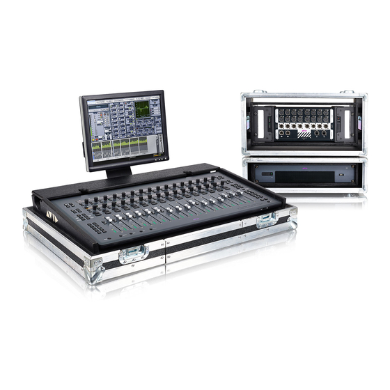
Chapter 1: Introduction to the VENUE | S3L-X System ® Welcome to the VENUE | S3L-X digital live mixing system from Avid . The S3L-X system includes the S3 control surface, the E3 en- gine, and up to four Stage 16 remote I/O boxes, providing a compact, modular, scalable, and high-fidelity live mixing solution using ul- tra-reliable and low-latency Ethernet AVB audio network connections. -
Page 13: S3L-X System Features
S3L-X System Features S3 Control Surface Features The S3 control surface provides system controls, mix position au- S3L-X System Processing dio I/O, and control and utility connections. The S3L-X system provides the following processing features System Controls and capabilities: • 64 input processing channels, each with built-in High-Pass •... -
Page 14: E3 Engine Features
E3 Engine Features Stage 16 Remote Stage Box Features The E3 engine provides mix position audio I/O, and connections Stage 16 provides remote stage I/O for S3L-X systems in a 4U for synchronization, utility and control. The E3 engine also rack-mountable enclosure. -
Page 15: What's Included
Activation Card The Avid S3L-X System Software & Plug-Ins What’s Included Activation Card is used to activate your S3L-X software and plug-ins. This activation process deposits the following iLok li- S3 Control Surface censes into your iLok account: • S3L-X plug-in licenses Each S3 control surface includes the following: •... -
Page 16: Additional Required Components
Additional Required Components Operational Requirements The following required components must be purchased sepa- Temperature and Ventilation rately: S3L-X system devices should be operated away from heat • Shielded Cat 5e (350 MHz) or better Ethernet cable with sources and with adequate ventilation. Neutrik etherCON connectors (for audio network connec- tions between components) Hardware monitoring and automatic warnings are provided... -
Page 17: Connection Requirements
Connection Requirements About www.avid.com The Avid website (www.avid.com) is your best online source for Power Connections information to help you get the most out of your system. The fol- lowing are just a few of the services and features available. Power connections on all S3L-X system devices are auto volt- age-selecting (100 to 240V nominal, 90-260V maximal, 50–60 Product Registration Register your purchase online. -
Page 18: Conventions Used In This Guide
SHIFT and SHIFT Lock Conventions Used in This Guide The SHIFT switch on the S3 is used in conjunction with other All of our guides use the following conventions to indicate menu keys to access secondary functions Some switches have second- choices and key commands: ary functions, highlighted in gray above the primary function (such as <... -
Page 19: Chapter 2. Configuring And Connecting
Chapter 2: Configuring and Connecting The chapter shows how to get your system up and running by do- Unpacking and Assembling System ing the following: Components • Unpack and assemble the components Unpacking System Components • Connect the power and peripherals (monitor, USB keyboard and mouse) Remove all components from the shipping packaging. -
Page 20: Connecting Power
Stage 16 Connecting Power The AC power input for the Stage 16 is located on the back/bot- S3 Control Surface tom panel of the box. One male, 3-pin North American standard IEC power socket with cable retaining tie is provided. The input The external PSU for the S3 control surface is connected to the and power switch are recessed to allow the box to sit on its back. -
Page 21: Connecting Peripherals
Connecting Peripherals Connecting an S3L-X System After connecting power and peripherals, make audio network Connecting a Monitor connections between system components. You can also make connections to Pro Tools, and to a router or client computer for A DVI connector is provided on the E3 engine to connect a remote control of your S3L-X system using ECx Ethernet Con- DVI-D compatible video monitor (not included). - Page 22 Connecting a Basic System This section shows how to connect a basic system comprised of a single S3, a single E3 and up to four-Stage 16 boxes. Make redundant audio network connections by connecting the last Stage 16 in the chain back to the E3 engine. To connect a multiple-Stage 16 system: Connect an Ethernet cable from Network port A on the back of the S3 control surface to Network port C on the E3 engine.
- Page 23 Connecting a Redundant Ring Network To connect S3L-X in a redundant ring network: Connect a supported Ethernet cable from Network port A on each S3 control surface to Network port C on the corresponding E3 engine. The S3 control surface must always be connected Network port C on the corresponding E3 engine. Daisy-chain the E3 engines together by connecting Ethernet cables between available Network ports on the E3 engines.
-
Page 24: Powering Up The System
Powering Up the System To power on the first Stage 16, do the following • Locate the power switch on the back of the Stage 16 and After connecting your system components, power up your sys- press the switch to the On position. The Status LED on the tem. -
Page 25: Confirming System Components
Confirming System Components Enabling Config Mode After connecting and powering up system components, you can There are two main operating modes for the S3L-X system, Con- confirm system components in the VENUE software screen. fig mode and Show mode. Use Config mode to accomplish tasks such as setting up your system, configuring options, loading To confirm system components: Show files, and installing software such as plug-ins and system... -
Page 26: Setting Up A Basic System
Click the flashing Identify button to unlatch it. Setting Up a Basic System Locate the Stage section. Empty Stage slots are indicated by When you initially configure a basic system, you assign Stage 16 the text Drag I/O Box Into Slot. boxes to available Stage slots in the Options >... -
Page 27: Setting Up A Shared Input Configuration
Assigning Stage 16 Remote Stage Boxes Setting Up a Shared Input Configuration After pairing S3 control surfaces to E3 engines, you can then as- sign Stage 16 boxes to available Stage slots in the Options > De- This section shows how to configure your system for sharing vices page. -
Page 28: Setting The System Clock
To assign a Stage 16 and designate your system as the Master for Setting the System Clock that Stage 16: Make sure your system is in Config mode. When you first work with a VENUE system, make sure the sys- tem clock time, date and time zone are set appropriately. -
Page 29: Managing Connections
Removing a Stage 16 Managing Connections You can remove a Stage 16 box from your configuration so that After the initial setup, devices on the network can be named and it does not appear in the Options > Device tab. Do this if you are renamed, reassigned, removed, and added to the current configu- removing a connected Stage 16 from your configuration, or if a ration. -
Page 30: How To Proceed
Managing Stage 16 Connections in Shared Input None Configurations The None command you disconnect the E3 from its currently After the initial setup, the next time your power on your shared paired S3. Use this option if you have paired to the wrong S3 on input S3L-X system, the previous Master/Slave relationships be- the network, or if you want to operate the E3 without an S3 and tween Stage 16s and E3s are maintained. -
Page 31: Audio And Control Connections, Switches, And Indicators
Audio and Control Connections, Switches, and Indicators Before making any audio connections, make sure your audio monitoring system is turned down or muted. S3 Control Surface Connections and Switches S3 control surface back panel Audio Connections S3 control surface audio I/O is assigned to VENUE system chan- nels using the Patchbay, under the Console tab. - Page 32 E3 Engine Connections and Switches 2 x IN 2 x OUT WORD CLOCK E3 engine back panel Audio Connections Control and Power Connections E3 engine audio I/O is assigned to VENUE system channels us- 6 – USB 2.0 Ports ing the Patchbay, under the Engine tab. Connect an iLok Smart Key (for plug-in authorization).
- Page 33 9 – GPI Port 10 – ECx Port A 9-pin, female DB9 connector provides a 2-in/2-out GPI Gen- This port provides connection to a computer or router to enable eral Purpose Interface (GPI). For specifications, wiring diagrams ECx Ethernet Control (remote control of the VENUE system). GPI Port Reference.
- Page 34 Stage 16 Connections and Switches Stage 16 Box front panel Stage 16 Audio Connections Stage 16 Control and Power Connections, Switches, and Indicators Stage 16 audio I/O is assigned to VENUE system channels under the Stage 1–4 tabs in the Patchbay. Each Stage 16 has its own tab 5 –...
-
Page 35: Installing Additional Software
Installing Additional Software After having unpacked, assembled, connected, and powered up your S3L-X system, you can manually install any additional soft- ware, as follows: VENUE Software Update A VENUE software update may be available for your system. If an update is available, download and install it. -
Page 36: Part Ii Description
Part II: Description... -
Page 37: Chapter 3. S3L-X System Control Overview
Chapter 3: S3L-X System Control Overview This chapter provides an overview of S3L-X system controls on the console and on-screen. Most VENUE features and controls that are used during a performance are available from both the console and on-screen. Changes made on one are immediately reflected in the other, letting you use almost any combination of console and screen controls to mix. -
Page 38: Channel Section
Channel Section The Channel section provides 16 channel strips to control input and output channels. Each channel strip has a fader, an assignable chan- nel encoder to control adjustable channel parameters, and a display to show channel and associated parameter information. Channels are banked (assigned) to channel strips using the A–F and User bank switches, as well as the <... - Page 39 Channel Encoder Assignment Switches Level Meter Shows input level for input channels, and output level for output channels. Clipping at various points in the chan- The Channel Encoder Assignment switches assign channel pa- nel signal path is also indicated when the top most LED lights red. rameters to the channel encoders.
- Page 40 Fader Banking Controls Aux Assigns control of Aux (and Variable Group) send levels to the channel encoders. S3L-X provides controls for banking channels in layers and for When the Aux switch is pressed, the Aux Select menu appears banking channels horizontally. ...
- Page 41 < Nudge > and < Bank > Switches Multi-Assign, OK, and Cancel These switches let you bank channels to Channel strips sequen- These switches let you enter, confirm, cancel and exit multi-as- tially. signment and multi-selection modes, and on-screen dialog boxes. Mixer Close Nudge...
-
Page 42: Channel Control
Channel Control Channel Control provides consistent control and display of channel processing functions such as EQ, dynamics, and Auxes for the cur- rently selected input or output channel. Channel Control features eight encoders, each with a corresponding Select ( Sel ) switch, In switch, display, and color-coded LED. - Page 43 Channel Control Navigation Switches Channel Control Displays The Channel Control displays show the Channel Control main The Channel Control Navigation switches let you navigate menu. When a processing function is assigned to Channel Con- through the available pages of Channel Control parameters. A function In (enable/bypass) switch is also provided, as well as a trol, the displays show the available parameters.
-
Page 44: Global Controls
Global Controls Global controls provide control of global parameters and functions such as control of output bus levels, Matrix input and output levels, Monitor bus levels, screen navigation, and programmable events. Controls include eight Global Control encoders with associated switches and displays, six View Mode switches, eight customizable Function switches, Monitoring switches, a Touch Strip, Global Modifier switches, and two SHIFT switches. - Page 45 View Mode Switches Global Control Navigation Switches The Global Control Navigation switches let you navigate The View Mode switches provide navigation for the on-screen through the available pages of Global Control parameters. A software pages and tabs. switch for toggling system operating modes is also provided. View 1 View 2 Config...
- Page 46 Function Switches Monitoring Switches The Function switches can be customized to control a wide range The Monitoring switches provide controls for the VENUE Solo of console parameters such as Mute Groups, snapshot recall, tap and Monitor busses. tempo, and transport controls for Pro Tools and built-in 2-track USB recording and playback.
- Page 47 To adjust a control with fine resolution using only the key- Multi Select Default Fine Command board and mouse, Ctrl-click the on-screen control and adjust. SHIFT CTRL Momentary and Latching Modes Global Modifier switches Multi-Select (Shift) The Fine switch supports momentary and latching operation. The Multi-Select switch lets you select multiple input channels Momentary In momentary mode, the Fine switch stays in effect and then apply an action to all selected channels for batch routing...
-
Page 48: Software Screen Overview
Viewing Page and Tabs Software Screen Overview To view a page, do one of the following: The screen is not required in order to mix a performance, as all es- Press the View Left or View Right ( ◄ ► ) switch to cycle sential mixing controls are provided on the console. - Page 49 Overview of Software Pages Filing The software screen provides the following pages and tabs. Load, save, and transfer shows and presets, and access the con- sole History. Inputs Select, name, configure, and adjust parameters for input channels and FX Returns. Filing page (History tab) Shows and File Management.
- Page 50 Patchbay Media Patch input and output channels to hardware inputs and outputs, Configure, control, and monitor 2-track USB recording and play- and name channels. back. Media page (Playback tab shown) Patchbay page (Inputs tab shown) 2-Track USB Recording and Playback. Patchbay.
- Page 51 Channel Color Coding You can color-code on-screen fader strips and corresponding channel display LEDs to help identify key channels or groups of channels faster. To set a channel color: Right-click a fader strip on-screen, or select multiple channels and right-click any of the multi-selected faders. Set Channel Color From the pop-up, select and choose one of...
-
Page 52: Chapter 4. Banking And Selecting Channels
Chapter 4: Banking and Selecting Channels Banking FX Returns Banking Channels When your system is configured with 48 Input Channels plus The S3L-X system provides channel banking controls to navigate eight FX Returns, Bank switch D banks FX Returns 1–8 to the to channels beyond the number of available physical faders. - Page 53 Banking with < Nudge > and < Bank > User Layouts Switches You can create custom channel layouts on the S3, and access < Nudge > and < Bank > let you bank through channels horizon- those layouts on the 16 S3 channel strips using the User Bank tally.
- Page 54 To assign multiple channels to a User Layout: To remove all channels from the current User Layout: Go to the Inputs or Outputs page. • Right-click any channel and select User Layout from the pop-up menu. Click the USER tab. •...
- Page 55 Saving User Layouts Channel 6 on Bank B is then Bank Safed. Selecting the various banks results in the following channel layouts: You can store and load User Layouts to disk as Preset files using Channel layout with Bank Safe enabled on channel 6 the User Layouts Preset Folder.
- Page 56 Using Bank Safe Special Cases Affecting Bank Safe Special rules and conditions are automatically applied to Bank To Bank Safe channels: Safe status whenever you do the following: Make sure you have enabled Bank Safe mode for the Channel • Banking GEQ to faders Safe switches.
-
Page 57: Selecting And Targeting Channels
Selecting Channels On-Screen Selecting and Targeting Channels To select a channel on-screen Channels can be selected on the S3 or on-screen. Selecting a Click anywhere in the on-screen fader strip, except on the channel targets that channel for processing in Channel Control or ... - Page 58 Selecting Multiple Channels To select the Aux and Groups/Variable Groups from the Global (Multi-Select) Control encoders: Make sure the Global Control main menu is shown in the Multi-Select lets you select multiple channels in order to apply an Global Control displays. action to them in one step, such as turning Aux sends on or off for Press the Aux/Grp Global Control encoder.
-
Page 59: Screen Controls
Adjusting On-Screen Encoders Screen Controls You can adjust on-screen rotary encoders by dragging directly Adjusting On-Screen Faders over the on-screen knob. To adjust an on-screen encoder: You can move on-screen faders independently or in ganged fash- ion. Click on the encoder so that it is highlighted. To adjust a single fader on-screen, do one of the following: Drag up to turn the encoder clockwise;... - Page 60 Reset Fader to 0 Parameters and Channel Types Resets the fader position to zero. Input channels can only be copied or pasted to other Input chan- nels. Output channels can only be copied or pasted to other chan- Reset Selected Input Strips nels of the same type (such as Aux, Group, or Matrix).
- Page 61 Make Selected Mono Strips Stereo/Make Blank Strips On-Screen Selected Stereo Strip Mono Blank strips appear as a simple gray strip with no fader, buttons or Combines two selected mono channels into a single stereo chan- meter. A blank strip can be right-clicked to reveal its context nel, or splits a selected stereo channel into two mono channels.
- Page 62 Fader and Encoder Shortcuts Automatically Inserting Blank Strips using Make Stereo VENUE automatically creates blank strips when you use the The on-screen channel faders and encoders provide the following Make Stereo command in order to preserve the current channel right-click shortcuts to reset individual parameters and channel layout.
-
Page 63: Type Text Search
Type Text Search Type Text search lets you use the keyboard for fast navigation to a channel, or to quickly go to a specific snapshot or event. You can enter the first characters of a channel name or the absolute channel number to target that channel on-screen or in Channel Selecting and Targeting Channels Control (see also... -
Page 64: Chapter 5. Channel Control
Chapter 5: Channel Control Channel Control provides consistent control and display of processing functions for the currently selected input or output channel. Ch 1 User Input CompLim Aux 9-16 Var Grps ExpGate Aux 1-8 Back Expnd Page Page The Channel Control main menu The following processing functions can be assigned to and controlled from Channel Control, and are shown in the Channel Control main menu: •... -
Page 65: Using Channel Control
Do any of the following to adjust parameters: Using Channel Control • Rotate the Channel Control encoder under the display show- ing the parameter you want to adjust. For example, to adjust Using Channel Control is as simple as selecting a channel, assign- the gain for the low band of a channel EQ, rotate the encoder ing a processing function to Channel Control, and adjusting the under the display showing Lo Gain . - Page 66 Channel Control LEDs To enable or bypass an entire EQ, Comp/Limp, or Exp/Gate function (toggle in/out), do either of the following: Each processing function has a unique color associated with it When the main Channel Control menu is shown, press the ...
-
Page 67: Assigning Functions To Channel Control
To create a custom User assignment in User Assignment mode: Assigning Functions to Channel Control Right-click any available encoder. Select Enter User Assignment mode from the menu. See the following sections for information on assigning and ad- justing processing functions using Channel Control: Click an on-screen encoder to assign control of the parameter to Channel Control encoder 1. -
Page 68: Expanding Channel Control
Expanding Channel Control When Channel Control parameters are expanded, either additional parameters for the currently assigned function or parameters for a dif- ferent function appear across the entire top-row of encoders, as follows: Expanded Channel Control Parameters Channel Control Not Expanded (Default) Channel Control Expanded Encoders 1-8 Encoders 9-16... -
Page 69: Availability Of Channel Control Functions
Availability of Channel Control Functions The functions available on Channel Control depend on the type of channel currently selected, as shown in Table 1. Functions are listed across the top row, and channel types are listed in the left column. Table 1. -
Page 70: Chapter 6. Options
Chapter 6: Options The Options page provides several tabs. Of these, the System and System Devices tabs are where most system configuration settings and (System Configuration) options are enabled and customized: • The System tab provides the primary tools by which you From the System tab you can configure input channels, configure configure mixing, routing, and processing options. - Page 71 System Configuration Settings Main Busses In Show mode, the System Configuration section is display-only, The Main Busses settings let you choose the overall configuration showing the current allocation of system resources and bus set- for the Main busses. tings. Configuring the Main Busses For instructions, see In Config mode, you can edit system settings such as input chan- Bus Configuration Settings...
- Page 72 Patch List Lists the contents of each Patchbay page. A complete Do any of the following: patch list is included in the System Information Export, or a de- • If you have more than one USB storage device connected, tailed patch list can be exported separately from the Patchbay (see make sure the correct USB device is selected.
-
Page 73: Busses
Troubleshooting MIDI and MTC While the system is locked: This section provides the following troubleshooting options: • Snapshots continue to be recalled via MTC, either internally Clear Console or externally generated. The Clear Console button resets all parameters on all channels to •... -
Page 74: Pickoffs
Solo and Monitor Operations Pickoffs These settings customize Solo and Monitor bus mode and opera- The Pickoffs tab lets you control the bus pickoff point on input tion. strips, as well as specify source and insert points for output bus- ses. -
Page 75: Snapshots
Aux Mon and Aux FX Snapshots These settings let you classify individual Aux Sends (including The Snapshots tab provides several snapshot preference settings linked bus pairs) as monitor sends (“Mon”) or as effects sends to optimize snapshot operation. (“FX”), which lets you scope each type separately from the Snap- shots tab. -
Page 76: Misc
Misc The system clock setting can affect data synchronization with Synchronizing Settings, portable storage devices. See The Miscellaneous (Misc) tab provides utility and other settings. Shows and Presets Show Time in Status Area You can choose to show time of day in the lower right corner of the screen in the Status display area. -
Page 77: Interaction
Meter Interaction The following display options can be configured for meters. The Interaction tab lets you configure behaviors for selected These options affect the 16 channel meters on the S3 control sur- channels, Input Safe Switches, Lights, Meter, Ethernet, and LCD face and on-screen. - Page 78 Ethernet Control Clip Hold Time The Clip Hold Time determines how long a clip indication lasts Ethernet Control settings let you configure the following: after the last clipped signal. Clip Hold Time can be set within a ECx Network Settings These settings let you configure ECx range of 0–20 seconds.
-
Page 79: Devices
Stage 16 Network Port A and B LEDs Devices When a Stage 16 is assigned to a Stage slot on the Devices tab, The Devices tab lets you view and edit system connections, edit on-screen LEDs are provided to indicate the status of the physical hardware settings, provides troubleshooting and diagnostic op- A and B Network ports on that device tions, and provides network information. -
Page 80: Events
Events The Events tab of the Options page lets you use the Event list to customize the function of switches, footswitches and General Purpose Interface (GPI)-connected devices. Events. For information, see Events tab of the Options page Plug-Ins The Plug-Ins tab of the Options page is used to install plug-ins on the system. -
Page 81: Part Iii Signal Routing
Part III: Signal Routing... -
Page 82: Chapter 7. Inputs And Input Routing
Chapter 7: Inputs and Input Routing This chapter describes how to do the following: Configuring Inputs • Configure system settings for input channels, including set- ting the input channel configuration, naming channels, com- The following two types of input channels are provided: bining two channels into a stereo channel, and reordering Input Channels Sources for Input Channels include Stage 16 channels... - Page 83 Setting the Input Channel Configuration Naming Input Channels You can choose one of the following input channel configura- Input Channel and FX Return channel names can be changed tions: from the Inputs page. Channel names can be up to 32 characters in length.
- Page 84 Combining Input Channels (Make Stereo) Splitting Stereo Channels Pairs of mono input channels can be combined to make stereo To split a stereo channel into two mono channels: channels, whose left and right sides are then controlled by one in- Put the system into Config mode.
-
Page 85: Assigning Input Sources To Channels
The channel source (hardware input) and its destination (channel Assigning Input Sources to Channels name/number) is shown above the hardware tabs. Inputs sources can be assigned to any Input Channel or FX Return using the Patchbay. In the Patchbay, each system component has a corresponding hardware tab that displays the available hard- ware input sources, as follows: Channel source and destination shown on the Inputs tab of the... - Page 86 Inputs from Pro Tools Assigning a Source to Multiple Input Channels The following types of inputs from Pro Tools are provided: A hardware input source can be assigned to multiple Input Chan- Virtual Soundcheck Inputs Any Input Channel with a Stage in- nels or FX Returns in the Patchbay (you can fan out a source to put as its source is automatically assigned a corresponding multiple channels).
-
Page 87: Routing Input Channels To Outputs
To route a channel to the Mains and Groups busses on-screen: Routing Input Channels to Outputs Select one or more channels. Input Channels and FX Returns can be routed to Mains and Do any of the following on-screen: Groups, and Matrixes. Signals from Input Channels and FX Re- •... -
Page 88: Routing Inputs To Direct Outputs
Configuring Aux Busses (Aux Sends) Adjusting Input Parameters The S3L-X system can be configured to have 8 Auxes and 8 ste- Input parameters can be adjusted on the S3 control surface or reo Groups, 16 Auxes and 8 mono Groups, or 16 Aux busses and on-screen. - Page 89 Setting Right Offset on Stereo Channels To adjust channel input gain from Channel Control: Select one or more channels to target them in Channel Control. On stereo Input Channels and FX Returns, the Gain control af- fects both the left and right channels. The Right Offset feature lets Make sure the Channel Control main menu is shown in the Channel Control displays ( User, Input, EQ, Comp/Lim, you offset the gain of the right channel relative to the left channel...
- Page 90 48V (Phantom Power) Stereo Width 48V phantom power can be applied to any analog input assigned Width adjusts the stereo image of stereo Input Channels and to an Input Channel or FX Return. FX Returns by controlling ganged pan positions of the left and right channels, in opposite directions.
- Page 91 Safe (High-Pass Filter) Safe toggles Automation Safe or Solo Safe on/off for Input Chan- nels and FX Returns, depending on the current Safe mode setting. A built-in 4th-order High-Pass Filter can be enabled on each In- Safe mode is enabled globally for Input Channels and FX Returns put Channel or FX Return.
-
Page 92: Using Built-In Eq And Dynamics On Inputs
Adjusting Input Controls On-Screen Using Built-In EQ and Dynamics on Inputs The software screen Input section lets you adjust input parame- ters on-screen. Each Input Channel and FX Return has a built-in 4-band EQ and two Dynamics processors: a Compressor Limiter (Comp/Lim) and an Expander/Gate (Exp/Gate). - Page 93 Using Built-In Dynamics on Inputs To engage and adjust the built-in Comp/Lim from Channel Control: Built-In Dynamics can be controlled from the Channel encoders, Select one or more input channels. Channel Control, and on-screen. An input/output curve appears on-screen when adjusting dynamics parameters. Make sure the Channel Control main menu is shown in the Channel Control encoder displays.
-
Page 94: Using Plug-In Inserts On Inputs
To toggle a plug-in on/off (in/out of circuit): Using Plug-In Inserts on Inputs Select the channel on which the plug-in is inserted. Plug-Ins are arranged in virtual racks, which allow signals to be Go to the Inputs page and click the in/out button next to the de- sent to and from each plug-in as if it were an external processor. -
Page 95: Input Channel Presets
To preview and recall a saved Channel Preset: Input Channel Presets Navigate to the Inputs page for the desired channel. Channel Presets can only be loaded into a single channel at a time. Input channel configurations can be stored and recalled as Input Channel Presets. -
Page 96: Working With Inputs In A Shared Input Configuration
Channel Compatibility The following additional capabilities are also provided: Filing All parameters, including input gain levels, can be stored When storing and loading Input Channel presets, remember the following: to and recalled from Show files and snapshots independently on Snapshots each E3. -
Page 97: Chapter 8. Outputs And Output Routing
Chapter 8: Outputs and Output Routing Auxes This chapter shows how to do the following: • Configure and name outputs Up to 16 Aux busses are available. The number of available • Assign outputs and busses to hardware outputs in the Patch- Auxes is set as part of the overall system Bus Configuration set- Configuring Aux and Group Busses. - Page 98 Configuring the Main Busses Select one of the three available bus configuration. The Main busses can be configured to operate as either: L–R plus Mono Pans signals between the left and right channels to the L–R bus, and sums signals to a separate mono bus. L–C–R Pans signals across left, center and right channels.
-
Page 99: Assigning Busses To Hardware Outputs
The name of the source (bus or mixer) and its destination (hard- Assigning Busses to Hardware ware output) is shown above the hardware tabs, and below the Outputs channel name in the Outputs and the Patchbay > Outputs tab. Mains, Groups/Variable Groups, Auxes, and Matrix mixer out- puts can be assigned to any hardware output on the system using the Patchbay. -
Page 100: Using Built-In Comp/Lim And Eq On Outputs
To engage and adjust the built-in Comp/Lim from Channel Using Built-In Comp/Lim and EQ on Control: Outputs Select one or more output channels. Each Mains, Aux, Group, and Matrix output channel has a Make sure the main Channel Control menu is shown in the built-in Compressor/Limiter (Comp/Lim) and a 4-band paramet- Channel Control displays. -
Page 101: Using Inserts On Outputs
Using Built-In EQ on Outputs Using Inserts on Outputs One of two EQ types can be selected for the built-in EQ, on a Software plug-ins and graphic EQs can be inserted on Mains, per-channel basis: a full-spectrum parametric digital EQ or an an- Groups, Auxes, and Matrixes. -
Page 102: Adjusting On-Screen Output Controls
Inserting Built-In Graphic EQs on Outputs Adjusting On-Screen Output Controls Built-in 31-band Graphic EQs can be inserted on Mains, Groups, The software screen Output section lets you adjust output param- Auxes, and Matrixes. 16 Graphic EQs are available. eters on-screen. To insert a Graphic EQ on an Output bus: Go to the Outputs page and select the bus where you want to insert the Graphic EQ. -
Page 103: Adjusting The Mains
Using the Global Control Encoders Adjusting the Mains The Mains Global Control encoder provides a single level control Mains can be adjusted using the channels strips and the Global for the currently linked Main busses. You can also assign each Control encoders. - Page 104 Unlinking Mains To toggle the mute status of each Main bus independently: From the Global Control encoders, do the following: You can unlink any of the three Main busses for discrete control • Press the encoder under the display showing Mains to as- of Mains levels.
-
Page 105: Direct Outputs
Mains Automatic Delay Compensation Direct Outputs You can set the S3L-X system to automatically compensate for Each Input Channel, FX Return, output bus, and Matrix mixer delays incurred by the use of Groups and insertion of plug-ins in features a Direct Output. Each channel Direct Output provides a the signal path to the Mains. - Page 106 Adjusting Direct Outputs Direct Output Pickoff Points Up to 12 dB of gain can be added to the Direct Output signal. Di- The “pickoff point” is the point in the signal path where the audio rect Output level controls are provided in Channel Control, and signal is sent to the Direct Output.
-
Page 107: Vcas
Inputs and Outputs Pages In the Inputs and Outputs pages, red VCAs “ghost” fader caps appear below the fader displays of channels that are currently assigned to one or more VCAs. VCA controls emulate the operation of traditional Voltage Con- trolled Amplifiers (VCAs). - Page 108 Using VCAs VCA/Group Spill VCA level and mute status can be controlled from the channel You can “spill” a VCA or Group so only its members are banked strips or the Global Control encoders. to the channel strips. Spill lets you quickly access only those channels assigned to a specific Group and immediately focus on To control VCA members from the channel strips: those channels, without needing to bank through channels.
-
Page 109: Automation Safing Output Channels
Resetting Bus Assignments Automation Safing Output Channels You can remove input assignments from a Group on-screen. Automation Safing a channel lets you suspend the effect of snap- shots on all parameters of the channel. Output Channel Safe To remove an input assignment from a bus: switches and buttons always operate in Automation Safe mode. -
Page 110: Working With Outputs In A Shared Input Configuration
Copying Assignments Between Busses Working with Outputs in a Shared Input Configuration You can copy the current input assignments from one bus to an- other bus of the same type. If the busses are linked, assignments In shared input configurations, the availability of the outputs and can be copied from other linked busses. -
Page 111: Chapter 9. Groups
Chapter 9: Groups Routing Groups to Outputs, Plug-Ins, This chapter shows how to do the following: GEQs, and Built-In Comp/Lim and EQ • Configure Group busses • Route Groups to Mains You can route Groups to hardware outputs and Direct Outs. You can also insert plug-ins and built-in Graphic EQs on Groups, and •... - Page 112 Group Output Mute To adjust Group output levels from the Global Control encoders Make sure the Global Control menu is shown in the Global To control the mute status of a Group output from the channel Control displays. strips: Press Bank switch F to bank Groups to the channel strips. Press the Back/Top Global Control Navigation switch to re- turn to the Global Control main menu.
-
Page 113: Group Spill
Group Output Polarity Invert (Phase Group Bus Signal Flow Options Reverse) Routing Signals to a Mono Group Bus The polarity of any Group output bus signal can be inverted Configuration (Phase Reverse). With stereo Group busses, only the left channel is inverted. - Page 114 Routing Signals to a Stereo Group Bus Configuration When configured as stereo busses, the eight Groups are fed as eight true stereo busses. To use stereo Group busses: Make sure the Group busses are configured as stereo busses. Configuring Aux and Group Busses. When routing channels to any of the Group busses, the Stereo Pan switch is lit yellow.
-
Page 115: Chapter 10. Auxes And Variable Groups
Chapter 10: Auxes and Variable Groups This chapter shows how to do the following: Click the checkboxes above any of the bus pairs to link or un- link each pair. • Configure Aux and Variable Group busses • Route Auxes and Variable Groups to outputs, Graphic EQs, and plug-ins •... -
Page 116: Routing Auxes And Variable Groups To Outputs, Eqs, Dynamics And Plug-Ins
Selecting Aux and Variable Group Pre Setting a Send to Pre-Fader Pickoff Points To set an Aux or Variable Group send to pre-fader: Each input channel Aux or Var Group send can be set as pre- or Go to the Inputs page and select the channel with the Aux send post-fader. - Page 117 Creating an Effect Send/Return From the list, choose Bus Outs > Aux (or Group for a Variable Group bus), then choose the desired mono Aux or Variable An effect send/return lets you send signals from multiple Input Group. Channels (using Aux sends) to effects plug-ins such as reverbs and delays.
-
Page 118: Adjusting Aux And Variable Group Send Controls
Press a channel encoder under the display showing the sends Adjusting Aux and Variable Group you want to assign to the channel encoders. For example, to as- Send Controls sign channel send controls for Aux bus 1, press the encoder un- der the display showing Aux 1. - Page 119 Adjusting Sends Using Channel Control Assigning Variable Group Sends to the Channel Encoders When adjusting sends using Channel Control, adjustments made to sends affect only the selected channel. To assign Variable Group sends to the channel encoders: Bank Input Channels and/or FX Returns to the channel strips. To control Aux or Variable Group sends in Channel Control: Press the Aux Channel Encoder Assign switch.
- Page 120 Adjusting Stereo Sends To pan a stereo linked send in Channel Control: Rotate the even-numbered encoder for that pair. For example, When Aux busses are linked, input signals are panned across the if Auxes 1 and 2 are stereo linked, rotate the encoder under the bus pair.
-
Page 121: Adjusting Aux/Variable Group Output Parameters
To create a level offset between linked Aux/Variable Group Adjusting Aux/Variable Group Output outputs: Parameters Bank the Aux/Variable Groups busses to the channel strips. Aux and Variable Group output parameters can be controlled us- Do either of the following: ing the channels strips or the Global Control encoders. You can •... - Page 122 Aux/Variable Group Output Mute Aux/Variable Group Output Delay Aux and Variable Group busses can be muted from the channel A variable delay (from 0 to 500 ms) can be applied to Aux and strips and the Global Control encoders. Variable Group busses from Channel Control. With linked bus- ses, delay is applied to both channels.
-
Page 123: Chapter 11. Matrix Mixers
Chapter 11: Matrix Mixers This chapter shows how to do the following: The S3L-X system provides eight mono (or up to four pairs of stereo-linked) Matrix mixers for setting up alternate mixes, fill • Configure Matrix mixers and delay feeds, and cue, monitor or press mixes. •... -
Page 124: Configuring Matrix Mixers
Linking and Unlinking Pairs to form Configuring Matrix Mixers Stereo Matrix Outputs The 12 inputs for each Matrix mixer can be any combination of The eight mono Matrix mixers can be linked in odd/even pairs to the following potential sources: form up to four stereo-linked pairs of matrix outputs. - Page 125 Linking and Unlinking Adjacent Matrix Snapshots Inputs All matrix settings, including Pan but excluding the stereo link status, are stored and recalled with snapshots. The stereo link sta- Adjacent inputs to Matrix mixers can be linked or unlinked on a per input pair basis.
-
Page 126: Assigning Input Sources To Matrixes
Configuring User Inputs Assigning Input Sources to Matrixes Each Matrix mixer can have its own set of eight assignable User To assign input sources to a Matrix mixer: Inputs. User Inputs for each Matrix are configured in the User As- sign panel of the Matrix Mixer tab. -
Page 127: Adjusting Matrix Mixer Input Controls
On-Screen Matrix Input Controls Adjusting Matrix Mixer Input Controls To control Matrix input source (“send”) levels on-screen: Input sources for the Matrix Mixers can be controlled from the Go to the Outputs page and select the Matrix mixer. Global Control encoders or on-screen. Click the Matrix Mixer tab to display the Matrix input controls. -
Page 128: Adjusting Matrix Mixer Output Controls
Clearing Matrix Mixer Settings Adjusting Matrix Mixer Output Controls You can clear mixer input assignments to quickly set all the input sources to None. Matrix Mixer outputs can be controlled using the Global Control encoders, or on-screen. To clear Matrix input assignments: Select one or more Matrix mixers you want to clear. -
Page 129: Snapshot Data And Parameters For Matrix Mixers
Matrix Mixer Output Processing Matrix mixer output processing can be controlled using Channel Control. To apply output processing to a Matrix mixer: Assign Matrixes to Global Control. Press the Global Control encoder Sel switch under the display showing the Matrix output you want to adjust. Make sure the main Channel Control menu is shown in the Channel Control displays. -
Page 130: Chapter 12. Patchbay
Chapter 12: Patchbay The Patchbay is used to assign Input and Output Channels, Direct Outputs, and Inserts to hardware inputs and outputs. The Patchbay also provides on-screen controls for the currently selected channel, and provides the ability to name input and output channels. Accessing the Patchbay To show the Patchbay screen: Click the Patchbay button on-screen. - Page 131 I/O Tabs Patching Grid Click to display and patch Inputs, Outputs, or Directs (Direct The Patching Grid shows hardware I/O across the top, and system Outputs). Other options in the Patchbay screen change to reflect channels down the left side. The available channel tabs and the currently selected I/O tab.
- Page 132 Naming Channels from the Patchbay Assigned I/O When a hardware connection is assigned, its connection is Channel names can be changed from the Patchbay. Channel dimmed in all Patchbay screens. This lets you see which hard- names can be up to 32 characters in length. When shown in the ware connections are in use without having to switch back and displays on the S3 control surface, names are abbreviated to fit forth between Patchbay screens.
-
Page 133: Navigating The Patchbay
Navigating the Patchbay Assigning Channels in the Patchbay Navigating to Channel Types Channels can be assigned using the mouse or the arrow keys on the keyboard. Channels can also be unassigned The Patchbay uses multiple pages to access different hardware I/O and channel types. - Page 134 Unassigning and Clearing Assignments Multiple Input and Output Assignments in the Patchbay To unassign a single channel in the Patchbay: A single hardware input source can be assigned to multiple Input Place the cursor over an assigned channel in the Patching Grid ...
-
Page 135: Warning When Stealing Inputs Or Outputs In The Patchbay
Warning when Stealing Inputs or Patch List Export Outputs in the Patchbay The Patchbay export generates a patch list in an easily readable The Patchbay indicates hardware outputs that are already in use format. by dimming the column number for that physical output. In addi- To export Patchbay information: tion, a dialog is shown if the patch will steal a hardware input or output that is already in use, asking you to confirm or cancel the... - Page 136 Contents of Exported Patchbay Information Exported Patchbay information is saved as an HTML file, and the file name includes the date and time of the export. Contents in- clude the following: VENUE Patch List Show Name, file path, date and time of Show file. Input and Output Patching (Stage, Engine, Console, and Pro Tools) Stage Inputs Hardware input numbers (1–16) and the channel...
-
Page 137: Chapter 13. Solo And Monitor Busses
Chapter 13: Solo and Monitor Busses Solo In Place (SIP) This chapter shows how to do the following: • Select a Solo mode (PFL, AFL, or SIP) SIP mode applies to Input Channels and FX Returns only. Solo In • Configure Solo and Monitor bus option Place sends the signal from the soloed channel to the Main and Monitor busses. -
Page 138: Configuring Solo And Monitor Options
AFL Follows Auxes Configuring Solo and Monitor Options When AFL Follows Auxes is selected, assigning an Aux Send to Solo and monitor options are configured in the Solo and Monitor channel encoders automatically solos that Aux bus. This speeds Operations section of the Options > Busses page. up AFL access, specifically for monitor mixing. -
Page 139: Using Solo
Soloing Multiple Channels Using Solo To solo multiple channels, do one of the following: Solo operation depends on the type of channel being soloed, and With the Auto Cancel option enabled, press the Solo switches on any selected Solo switch options. In all modes, a channel’s ... -
Page 140: Solo Safing Channels
Solo Bus Metering Solo Safing Channels When a channel or dynamics key input is sent to the Solo bus, its Solo Safing an Input Channel or FX Return prevents that channel signal is metered on the Selected Channel meters, temporarily re- from being implicitly muted when any other channel is soloed. -
Page 141: Using The Monitor Bus
Routing the Monitor Bus to Hardware Outputs Using the Monitor Bus To route the Monitor bus to hardware outputs: The Monitor bus routes signals to the Headphone output. The In the Patchbay, click to the Outputs tab, then click the Mains Monitor bus can also be routed to hardware outputs and to tab. -
Page 142: Adjusting Monitor/Headphone Level
Sending the Main Mix to the Monitor Bus To adjust the level for the Monitor bus on-screen: Go to Options > Busses . Monitor Output from an L-C-R Main Mix In the Solo and Monitor Operations section, adjust the The stereo Mix to Monitors signal is derived from the L–C–R Monitoring knob. - Page 143 Using Talkback Configuring the Oscillator and Setting Level The Oscillator is configured on-screen, and can be activating You can route a single Console or Engine analog input directly on-screen or from the Global Control encoders. into any output bus using the Talkback circuit. This allows you to send talkback to outputs (such as Auxes feeding stage monitors) To configure the Oscillator: without having to use a system channel.
- Page 144 Activating 2-Track Input and Setting Level To activate and set the level for the Talkback from the Global Control encoders: The 2-track input can be adjusted on-screen or from the Global Press the Monitoring Global Control encoder to assign Talk- Control encoders.
-
Page 145: Chapter 14. Muting And Mute Groups
Chapter 14: Muting and Mute Groups This chapter shows how to do the following: Using Mute Groups • Mute Channels Channels can be assigned to any of the 8 available Mute Groups. • Using Mute Groups Mute Groups let you mute and unmute multiple channels simul- taneously by pressing a single switch. - Page 146 Click the ADD button in the Triggers list and choose a Func- Do either of the following: • To confirm the Mute Group definition, click the flashing As- tion Switch from the pop-up menu. The Function switch, with its default properties, is added to the Triggers list. sign button.
- Page 147 Using Mute Groups Explicit and Implicit Channel Mute with Mute Groups and VCAs Mute Groups are activated using the Mute Group controls This section describes the behavior of channel Mute switches on-screen, or the Function switches on the S3 control surface if when used with Mute Groups and VCAs.
- Page 148 Disabling Mute Groups You can temporarily disable all Mute Group functions. When Mute Groups are disabled, all channels implicitly muted as a re- sult of Mute Group activation are unmuted. Channels can still be explicitly muted when Mute Groups are dis- abled.
-
Page 149: Part Iv Processing
Part V: Processing... -
Page 150: Chapter 15. Dynamics
Chapter 15: Dynamics This chapter shows how to do the following: Built-In Comp/Lim • Use the built-in Compressor/Limiter The built-in Comp/Lim defaults to compression, or can be • Use the built-in Expander/Gate switched to a limiter by setting the Ratio to its maximum setting. •... -
Page 151: Built-In Exp/Gate
Adjusting the Built-In Comp/Lim To engage and adjust Comp/Lim Threshold using the channel encoders: The built-in Comp/Lim can be adjusted using Channel Control Bank Input Channels and/or FX Returns. and on-screen. Comp/Lim Threshold can be adjusted using the Press the Comp Threshold Channel Encoder Assignment channel encoders. -
Page 152: Adjusting Dynamics Plug-Ins
Adjusting the Built-In Exp/Gate Adjusting Dynamics Plug-Ins The Exp/Gate can be adjusted using Channel Control and Dynamics plug-ins inserted on channels can be adjusted using on-screen. When adjusting Dynamics, a Dynamics response Channel Control. Dynamics plug-ins map their threshold, ratio, curve appears on-screen. -
Page 153: Input Direct Mode
To adjust dynamics parameters on-screen: Input Direct Mode Select a channel on-screen. Input Direct mode lets you completely bypass the built-in dynam- Adjust the on-screen controls as needed: ics and EQ processing, and all inserts on Input Channels and FX •... -
Page 154: Dynamics Settings And Presets
Presets for Built-In Dynamics Dynamics Settings and Presets You can store and load dynamics settings as presets for built-in Built-in dynamics settings can be copied and pasted between and plug-in dynamics processors. Presets can be accessed channels. Settings can also be stored and loaded as dynamics Pre- on-screen. -
Page 155: Using The Sidechain
Using External Key Sidechain Using the Sidechain The on-screen Key Assign selectors lets you select the side-chain Dynamics processors typically use the detected amplitude of their source for either dynamics processor and its pickoff point. input signal to trigger gain reduction. This split-off signal is known as the sidechain. - Page 156 Using Sidechain EQ Filters Key Listen Both the Compressor/Limiter and the Expander/Gate sidechains The Key Listen button toggles the key onto the Solo bus, replac- provide two bands of EQ to band-limit the range of frequencies ing the signal there. This happens regardless of whether the key is that trigger dynamics processing.
-
Page 157: Channel Control Dynamics Parameter Mapping
Channel Control Dynamics Parameter Control Ranges for Built-In Dynamics Mapping Comp/Lim Defaults and Ranges The following tables show how Dynamics parameters are mapped to the Channel Control encoders and their corresponding Comp/Lim (defaults to Compressor mode) In and Sel switches. Parameter Default Minimum... -
Page 158: Chapter 16. Eq
Chapter 16: EQ This chapter shows how to do the following: EQ Overview • Use the built-in EQs Built-In EQ • Use the Graphic EQs • Adjust EQ plug-ins A 4-band parametric EQ is available on each Input Channel, FX •... -
Page 159: Built-In Eq Parameters
Q (Q/Bandwidth) Controls Q (in digital mode) or bandwidth (an- Built-In EQ Parameters alog mode). 4-Band EQ In Digital mode, Q determines Q factor. When the Hi or Lo fil- ters are in Shelf mode, the Q knob determines the Q of the shelf. The following 4-band EQ parameters are available: In Analog mode, this control changes to a bandwidth control ... -
Page 160: Adjusting Eq
To adjust the built-in HPF from Channel Control: Adjusting EQ Select one or more input channels. You can adjust EQ from the Channel encoders, Channel Control, Make sure the Channel Control main menu is shown in the and on-screen. When adjusting EQs, an EQ response curve ap- Channel Control displays. - Page 161 EQ Parameter Mapping in Channel Control To engage or disengage a band: Press the Channel Control encoder In switch for that band to 4-Band Parametric EQ (Digital Mode) toggle it in/out. When engaged, the In switch LED is lit. The following table shows how built-in EQ parameters (default To bypass the current EQ module: digital EQ mode) are assigned to the Channel Control encoders:...
- Page 162 On-Screen EQ Controls Adjust the on-screen controls by doing one of the following: • Turn an on-screen knob ( Gain, Q/Bandwidth , or Fre- You can adjust the built-in 4-band EQ using dedicated on-screen quency ) for each frequency band. buttons for band in/out and bell/shelf toggling.
-
Page 163: Adjusting Eq Plug-Ins
Adjusting EQ Plug-Ins Graphic EQ for Outputs EQ plug-ins can map their gain, frequency, and Q/bandwidth Up to 16 built-in 31-band Graphic EQ can be inserted on any of controls to corresponding encoders in Channel Control. the output busses (Mains, Groups, Auxes, and Variable Groups) and Matrix mixers. -
Page 164: Input Direct Mode
Enabling and Adjusting Graphic EQ Input Direct Mode Graphic EQs are enabled and adjusted on-screen. Input Direct mode lets you completely bypass the built-in dynam- ics and EQ processing, and all inserts on Input Channels and FX To enable the graphic EQ: Returns. - Page 165 Presets for Built-In and Graphic EQ To save or load a preset for the Graphic EQ: Go to the Outputs page for the channel on which the graphic You can store and load EQ settings to disk as Preset files. Presets EQ is assigned.
-
Page 166: Control Ranges For Built-In 4-Band Eq (All Modes)
Control Ranges for Built-In 4-Band EQ (All Modes) Table 3. Control ranges for built-in parametric EQ Band Control Range (Digital) Defaults (Digital) Range (Analog) Defaults (Analog) High Frequency 20 Hz to 20 kHz 10 kHz 2 kHz to 20 kHz 6 kHz (Bell/Shelf) Gain... -
Page 167: Chapter 17. Plug-Ins
Chapter 17: Plug-Ins Using Config and Show Modes for Plug-Ins This chapter explains how to configure plug-ins before a perfor- mance, and how to use plug-ins during a performance. Plug-Ins The current system mode status (Config or Show mode) deter- can be inserted on all channels and bus outputs, or used as bus mines which plug-in functions are available. - Page 168 Installing Plug-Ins In the Plug-Ins to Install list, click the device selector pop-up menu and do one of the following: To install a plug-in: • Choose Previous Installs to access any plug-in installers af- Insert the USB drive containing the plug-in installer(s) into an ter a system update.
- Page 169 Removing Plug-Ins Deleting Uninstalled Plug-Ins Uninstalling a plug-in removes the plug-in from the racks but the Once a plug-in is uninstalled, its installer can be deleted from the installer remains in the Previous Installs cache, making it easier to system. (Plug-ins which are currently installed cannot be de- reinstall the plug-in at a later time without requiring the installer leted).
- Page 170 Authorizing Plug-Ins Automatically Removing Plug-ins During Show Load A core set of plug-ins are installed on your S3L-X system. These Plug-ins are verified during the Show file load procedure to plug-ins do not require any authorization. Other plug-ins, such as streamline plug-in lists and menus by automatically removing un- the S3L-X plug-ins downloaded from your Avid account and paid used plug-ins (plug-ins that were once installed but subsequently...
-
Page 171: Plug-In Version Checker
Using System Info to View Plug-in Version Plug-in Version Checker Information VENUE software includes a comprehensive database of plug-in Plug-in version information is included in exported System Info information, and this info can be used to greatly simplify the pro- data. -
Page 172: Plug-In Racks
Plug-In Racks The Plug-Ins page provides four plug-in racks. Each of the racks has five slots into which you can load a plug-in. The four different racks can be viewed all at once, individually, and in varying zoom levels. You populate the racks by assigning plug-ins in rack slots. Plug-In racks Zoom Toggle Presets... - Page 173 “Jump To” Plug-Ins Pinning a Plug-In View You can “jump to” a specific plug-in insert from the Input and You can decouple the plug-in view for consistent and constant ac- Output pages to adjust it on-screen in the Zoom view of the cess to a single plug-in on-screen, while still being able to select Plug-In page.
- Page 174 Identifying Rack Slots Unavailable Plug-Ins The racks indicate which plug-in is currently targeted by high- When a plug-in cannot be used because of insufficient DSP re- lighting its rack slot controls in blue. sources, because it is disabled, or because it is not installed on the system, a warning icon is shown in front of the affected plug-in.
-
Page 175: Rack Slots
Channel Insert or Bus Output The Channel Insert/Bus Output Rack Slots pop-up menu displays different choices depending on whether the plug-in is being used as a channel insert, or as a bus processor, Each rack provides ten plug-in slots. You can assign any installed as follows: plug-in to any available rack slot. - Page 176 Assigning Plug-Ins to Rack Slots Moving and Copying Plug-Ins (Config Mode Only) Before a plug-in can be used to process audio, it must be assigned to a rack slot. Once assigned, you can use the plug-in as a channel To move or copy a plug-in from the rack, drag the plug-in icon to insert or bus processor.
-
Page 177: Routing Plug-Ins
To insert a plug-in on a channel from the Plug-Ins page: Routing Plug-Ins Make sure the plug-in is already assigned to a rack slot. (See Assigning Plug-Ins to Rack Slots After a plug-in has been assigned to a rack slot, you can specify its routing. - Page 178 Routing a Plug-In as a Bus Processor When a bus-fed plug-in has both its input source and output as- signed, it appears similar to the following in the rack: Plug-Ins can be used on busses for send-and-return processing with effects such as reverb and delay. A plug-in is configured for bus processing by assigning an Aux, Group, Matrix, Main, Mon- itor output, or an Input Channel Direct Out as the plug-in input source, then assigning the output of the plug-in to an Input Chan-...
-
Page 179: Adjusting Plug-Ins
Side-Chain Routing Adjusting Inserted Dynamics and EQ Plug-Ins S3L-X supports sidechain (key) processing for plug-ins that sup- To access plug-in EQ, Comp/Lim, or Exp/Gate parameters in port side-chain triggering. Channel Control: Side-chain routing is not stored in snapshots. Select a channel with an EQ or Dynamics plug-in inserted. The Side-Chain selectors appear across the top of the plug-ins Make sure the Channel Control main menu is shown in the screen. -
Page 180: Bypassing Plug-Ins
Adjusting Plug-Ins Using Global Control Adjusting Plug-Ins On-Screen (Insert Mode) To adjust a plug-in on-screen: Selecting the Inserts Global Control encoder places Global Con- Select a channel. trol into Insert mode. In Insert mode, plug-in parameters are as- Go to the Plug-Ins page. signed to the eight Global Control encoders and their correspond- ing In and Sel switches. -
Page 181: Plug-In Presets And Snapshots
Snapshots Plug-In Presets and Snapshots Snapshots can automate plug-in settings, including routing, and You can save and load plug-in Presets files to import, export, and in/out state. (Side-chain routing is not supported in Snapshots.) transfer plug-in settings files. Snapshots can also store and recall Tempo. Snapshots can also be used to automate changes to plug-in rout- Snapshots do not store or recall Presets. -
Page 182: Plug-In Dsp Usage
Plug-Ins and VENUE Standalone Software Plug-In Levels You can use VENUE Standalone software to pre-configure Meter levels on the S3L-X system are displayed in dBVU, with plug-in routing and in/out state, with the following limitations: 0 dBVU =+4dBu analog out = –20dBFS. •... -
Page 183: Chapter 18. Hardware Inserts
Chapter 18: Hardware Inserts This chapter explains how you can connect external analog and Assigning Hardware Inserts to digital hardware to the analog and digital I/O on the S3 control Channels surface and the E3 engine for use as hardware inserts. Hardware inserts can be used for external processing on individual Input You can assign hardware inserts directly from the Inputs or Out- Channels, FX returns, Mains, Groups, Auxes, and Matrixes. -
Page 184: Activating And Bypassing Hardware Inserts
To assign a hardware insert from the Patchbay: Activating and Bypassing Hardware Go to the Patchbay page and click the Inserts tab. Engine and Inserts Console hardware tabs are shown. You can toggle hardware inserts in/out on-screen. Click the Channels, FX Returns, or Outputs tabs to show the desired channel types in the grid. -
Page 185: Part V Shows
Part VI: Shows... -
Page 186: Chapter 19. Shows And File Management
Chapter 19: Shows and File Management Creating Show Folders Data can be stored, recalled and transferred between VENUE systems. There are three types of information files that can be To create a new Show Folder: managed separately, as follows: Go to the Filing page and click the Save tab. Show Files These files are used to store, recall and transfer sys- In the Show Folders column, click the New button. -
Page 187: Loading A Show
Show Files Renaming Show Files Creating and Saving Show Files To rename a Show file: In the Shows column, click a Show file name to select it. When you create a new Show file, it captures the current state of In the Shows column, click the Rename button. -
Page 188: Working With Presets
System Configurations and Loading Preset Folders Shows Preset Folders contain Preset files. Each of the built-in processors Show files include system configuration settings such as the type (Compressor/Limiter, Expander/Gate, 4-band EQ, 31-band of control surface; the number of Mix Engines; Number of Input Graphic EQ) and each plug-in has its own Factory Defaults Channels, FX Returns, and EQs;... - Page 189 Renaming Preset Folders Click the Preset Folder name and choose a Preset Folder from the pop-up menu. Any Presets in the folder appear in the left To rename a Preset Folder: column. In the left column, click a Preset Folder name to select it. Click the Rename button.
-
Page 190: Transferring Settings, Shows And Presets
• To transfer Scope Sets for Recall Safe, click the Scope Sets Transferring Settings, Shows and icon. Presets You can copy Console Settings, Shows, and Presets to and from a portable storage device (such as a USB flash drive) for backup, transfer from standalone software, and transfer between systems. -
Page 191: Undoing Changes Using The History Feature
To synchronize Settings, Shows, or Presets between the VENUE The Notes field for each auto-saved Show file includes a descrip- system and a portable storage device: tion of the conditions that caused the automatic save. Go to Filing > Transfer . Several conditions cause the system to automatically save a new Connect a portable storage device (such as a USB flash drive) Show file in the History tab, as follows:... -
Page 192: Chapter 20. Snapshots
Chapter 20: Snapshots Snapshots let you flexibly store and recall a wide range of mixing parameters. Snapshots are commonly used to store the mixer setup and levels for individual scenes, songs or sound cues in a performance. Snapshots store information about channels and mix parameters, and you can use a variety of methods to edit, preview, and manage snapshot data. - Page 193 Main and Recall Safe Tabs Recall Buttons The Snapshots page provides Main and Recall Safe tabs. The Recall Previous (–) and Recall Next (+) buttons at the top of the Snapshots list cause the previous or next snapshot in the list to Main Provides the primary snapshot controls.
- Page 194 Selecting Snapshots Centering the Snapshot List The Options > Snapshots page provides a preference setting to You can select single snapshots or multiple snapshots in order to target, recall, duplicate, edit, lock or delete them in the snapshots always center the Snapshot list on the last recalled snapshot. This list.
- Page 195 Snapshot Scope Controls Channel Scope Controls When you create a snapshot, it captures the current state of all Channels are included or excluded from snapshots by clicking system settings. However, you can select which of these settings them on-screen in the Snapshot Channel Faders display. The you want to be recalled when you recall a particular snapshot.
- Page 196 Selected Channel Indication Channel Scope Action Buttons All Turns on the scope for all channels displayed on the current The Snapshots page indicates the currently selected channel. tab (such as 1–48). Double-clicking the All button turns on the If the selected channel is not scoped in the currently selected ...
-
Page 197: Creating Snapshots
Naming Snapshots Creating Snapshots New snapshots are automatically numbered and appear as “<Un- Snapshots can be created at any time to store the current channel titled>” in the Snapshots list. Snapshots can be renamed at any and parameter settings. You can create new snapshots manually time. -
Page 198: Recalling Snapshots
Recalling Successive Snapshots Instantly Recalling Snapshots You can instantly recall successive snapshots in the Snapshots list. This command references the currently recalled snapshot, not You can also target and recall snapshots using the Snap- the targeted snapshot. Snapshot Data shots Global Control Encoder. See Types and Parameters for more information. - Page 199 Selecting and Recalling Multiple Snapshots To target and recall using the spilled Snapshots controls: From the Global Control main menu, press the encoder under You can select and recall multiple snapshots to load them all in Snapshots the display showing to spill snapshot controls to the sequence, and in one step.
-
Page 200: Recall Safe
Recall Safe Displays and Controls To store a snapshot: Spill snapshot controls to the Global Control Encoders. Store Rotate the encoder under the display showing to target the snapshot you want to overwrite. X-Fade Store 0.0 s 1. Intro Back Expnd Page Press... - Page 201 5 – Scope Sets Parameter Matrix Grid Icons The display state of the Parameter and Channel grid icons indi- Scope Sets are presets for the Recall Safe tab that can be stored cate safe status for that column or row as follows: and loaded, just like plug-in, EQ and dynamics presets.
- Page 202 Using Recall Safe To safe all parameters across all channels and clear any current settings: To access the Recall Safe tab: Click the triangular icon at the top of the ALL column. Go to the Snapshots page and click the Recall Safe tab. You can undo or redo the last action taken in the parameter Click a Channel Type tab to display the desired channels.
- Page 203 Using Scope Sets Plug-Ins When engaged, this button prevents plug-in control settings, The configuration of the Recall Safe tab can be stored as a Scope in-circuit state, and routing from being recalled. Set settings file. Scope Sets can be previewed, recalled and trans- ferred just like plug-in, EQ and dynamics settings.
-
Page 204: Automation Safe
Automation Safe Managing Snapshots Automation Safing a channel lets you suspend the effect of snap- You can manage snapshots in the list by storing, locking, clear- shots on all parameters of the channel. ing, duplicating, deleting, or moving them. Output channel Safe switches and buttons always operate in Au- Storing Snapshots tomation Safe mode. - Page 205 Locking Snapshots Available Operations with Locked Snapshots Snapshots can be locked to prevent them from being accidentally The following table details which operations can or can not be altered, overwritten or deleted. performed on a locked snapshot. Locked snapshots can be selected, recalled, moved and dupli- Allowed Disallowed Operation...
- Page 206 Duplicating Snapshots Importing Snapshots Snapshots can be duplicated from the Snapshots list. You can Snapshots from other Show files can be imported into the cur- rently loaded Show file in the Filing > Load/Save tabs. undo Duplicate commands. To duplicate snapshots: To import Snapshots: Go to the Filing page and click the Load or Save tab.
-
Page 207: Making Changes To Snapshots
Absolute and Relative Edits Making Changes to Snapshots Changes can be applied to one or more selected snapshots as ab- There may be situations where you need to change specific pa- solute or relative values. Any parameter can be edited in absolute rameters in existing snapshots while leaving other parameters un- fashion;... -
Page 208: Preview Mode
Using Propagate Mode Preview Mode You can use the Propagate command to capture changes and ap- Preview mode lets you recall, store and edit snapshots without af- ply them to existing snapshots. Propagate mode is most useful fecting the current mix. when you realize during the course of mixing that you want to capture your current settings to use in other snapshots. - Page 209 Undo and Preview Mode Recall and Edit an Existing Snapshot Recall a snapshot to preview its settings and make any adjustments necessary, being In Preview mode, you can Undo actions applied to the Snapshot sure to re-store the snapshot before exiting Preview mode. Stor- List (such as Recall, Store, New and Duplicate) without affecting ing a snapshot in Preview mode does not affect previously stored the online mix.
- Page 210 Available and Unavailable Functions in Not Available in Preview Mode Preview Mode The only controls not available while in Preview mode are those In order to maintain essential mix indicators and controls while in controls which are not able to be stored or recalled via snapshots. Preview mode, not all functions are taken offline.
-
Page 211: Undoing Snapshot Commands
Plug-Ins in Preview Mode Undoing Snapshot Commands Recalling a snapshot that contains plug-in data affects the offline The Undo function returns the system to the state immediately (Preview) routing and bypass state of the plug-in only; the online before the last snapshot command. Undo is multi-level (up to plug-in parameter settings are not recalled, and the online mix is 100), is available while in Preview mode and after performing an not affected. -
Page 212: Adding Midi, Plug-In, And Media Data To Snapshots
Adding MIDI Messages to Snapshots Adding MIDI, Plug-In, and Media Data to Snapshots To add a MIDI message to a snapshot: Target the snapshot you want to modify. MIDI, Plug-Ins, and Media (USB 2-track transport commands) data are added to snapshots using the MIDI/Plug-In/Media list. Double-click the MIDI icon in the MIDI/Plug-Ins/Media list Open the list to add and edit data. - Page 213 Adding Plug-In Data to Snapshots To edit a MIDI message in the MIDI list: Double-click the message text to display the pop-up menu bar When the Plug-In data type is scoped for a snapshot, plug-in rout- for the message. ing, in/out state, and settings are recalled with the snapshot. (Add- ing or changing plug-in side-chain routing is not supported in snapshots.) The Snapshots Plug-Ins list lets you select multiple plug-ins and...
- Page 214 Updating a Plug-In Across Multiple Snapshots To add a plug-in to multiple snapshots from the Plug-Ins page: Create a multi-selection of snapshots in the Snapshots list. To update a plug-in across snapshots from the Snapshots page: Go to the Plug-Ins page. Select an individual snapshot, or create a multi-selection of Click the Snapshots menu for the plug-in to be added and snapshots in the Snapshots list.
- Page 215 Adding Media Data to Snapshots Adding Tempo Data to Snapshots When the Media data type is scoped for a snapshot, one of the fol- The Snapshots list can be toggled to display Tempo, along with a lowing USB 2-track Transport commands is available per snap- Tempo On/Off indicator for each snapshot entry.
- Page 216 Storing and Recalling User Layouts in To toggle tempo on/off for each snapshot: Snapshots Make sure Tempo is shown in the Snapshots list (if not, right-click any item in the list and choose Show Tempo ). You can store one User Layout per snapshot, providing up to 999 Click the Tempo icon so that it is lit (enabled) or unlit (dis- User Layouts per Show file.
-
Page 217: Snapshot Options
Special Cases for Crossfade Bypass Snapshot Options Incoming MIDI Commands Crossfade Time The snapshot crossfade is not bypassed if a MIDI Program Change message recalling the same snapshot is received during You can set the X-fade (crossfade) time for the channel faders be- the crossfade. - Page 218 Classifying Aux Sends You can classify Aux Sends as monitor sends (“Mon”) or as ef- fects sends (“FX”), which lets you scope each type separately from the Snapshots tab of the Options page. This option is only a means of organizing Aux Sends for snapshot control, and does not directly affect Aux bus op- eration.
-
Page 219: Snapshot Data Types And Parameters
Snapshot Data Types and Parameters Table 5. Snapshot data types and parameters included in each data type Snapshot Data Type Included Parameters (for Each Scoped Channel Strip) Fader Main volume level Mute Mute state EQ type selection (analog/digital); EQ in-circuit state; 4 bands (2 bands on FX Returns) of gain, freq, Q, bell/shelf selection (digital only), band on/off Compressor/Limiter in-circuit state;... -
Page 220: Chapter 21. Events
Chapter 21: Events Terminology This chapter introduces the Events tab, and explains how to use the Event list. Event A user-defined combination of one or more triggers and one or more actions. Each event serves as a type of software “macro”... -
Page 221: The Events Tab
The Events Tab The Events tab of the Option page is the working area of the Event list system. Events are defined and managed using the Event list, along with the Triggers and Actions lists. The lists and commands available in these sections create a powerful, user-programmable en- vironment. - Page 222 Event List Triggers Each event is shown in its own row within the Event list. The list The Triggers list shows the name and properties of each trigger can be scrolled vertically when necessary. defined for the currently selected event, as well as commands to create and manage triggers.
- Page 223 Actions GPI I/O Stats Display The Actions list shows the actions defined in the currently se- The GPI port on the back of the E3 engine can be used to trigger lected event, as well as commands to create and manage actions. events in VENUE from outboard equipment (GPI input), or can be used to send messages to trigger outboard equipment to per- form one or more actions (GPI output).
-
Page 224: Creating Events
Moving Events Creating Events Selected events can be dragged and dropped to new locations in The basic steps to create an event include the following: the list. You can also manually edit the event number to re-se- Adding an Event •... - Page 225 Deleting and Clearing an Event Toggling Enable Status for Selected Events Deleting an event removes it permanently from the Event list. To toggle the enable/disable status of an event in the list: Clearing an event leaves the named event in the Event list but Select one or more events in the Event list.
-
Page 226: Creating Triggers
Editing Trigger Type and Properties Creating Triggers To edit the trigger and its properties: Each Event can have up to eight triggers. You create new triggers Double-click the trigger row in the list. Or right-click the ac- by selecting them from the Add pop-up menu. Once added, you tion item and choose Edit . - Page 227 Managing Triggers in the Triggers List Examples of Logical Operators Logical operators determine the precise state required in order for Triggers in the list can be edited, duplicated and deleted. an event to occur as shown in the following tables: Editing Triggers OR At least one of the triggers must be true.
-
Page 228: Creating Actions
Editing an Action Type and Properties Creating Actions To edit an action: Each event can have up to eight actions. You create new actions Double-click the action row in the list. Or, right-click the ac- by selecting them from the Add pop-up menu. Once added, you tion item and choose Edit . -
Page 229: Testing Events
Action Wait Resetting Events All actions let you specify a Wait time of up to 100 seconds for You can use the Reset features to quickly reset Active or in-Test the action to wait before firing. This can be useful for synchroniz- events to “ready.”... -
Page 230: Snapshots And Events
Avoid Feedback Loops Snapshots and Events Because events can both affect and be affected by snapshots, it is Events can include snapshot functions among their triggers and possible for events to cause “feedback loops.” actions. Be especially careful when Recall Previous or Next snapshot trig- Snapshots as Triggers gers and actions are combined with events that recall a specific snapshot, as shown in the following diagram. -
Page 231: Default Settings, Templates And Examples
Default Settings, Templates and Examples Default Events Each Demo Show file contains a set of default events that can be used as a starting point to build your own events. Some examples of the types of default events include the following: Examples of default events Default Event Type and Name Triggers... -
Page 232: Tap Tempo For Plug-Ins
Using the Templates To quickly test the switch trigger, click the Test button, or press the Footswitch. Adjust the trigger State for your To add any of the events listed in the table, do the following (us- footswitch, as necessary, for its open/closed orientation. (For ing the first template, Talkback (Toggle) as an example): Editing Trigger Type and Properties instructions, see... - Page 233 Tips for Using Tap Tempo Create a Tap Tempo Event The plug-in Tempo Sync switch enables/disables that individual To create a Tap Tempo event plug-in’s delay value from following the system tempo. Use the Go to Options > Events . individual plug-in Tempo Sync switches to sync one, some or all Create a new event and call it Tap Tempo.
-
Page 234: Trigger Types
Trigger Types The following table lists the available trigger types and properties, along with a description of each. Table 6. Trigger list, with default settings Trigger Type Property 1 Property 2 Description Fader Above Channel name/number Fader level –inf to +12 dB Fader moved above threshold level (Default: –60 dB) Fader Below... -
Page 235: Action Types
Action Types The following table lists the available Action types and properties, along with a description of each. Table 7. Action types Action Type Property State Behavior Description Target Next Channel Selected Channel advances by Target Previous Channel Selected Channel reverses by Copy Selected Channel Channel copy operation Paste to Selected Channel(s) - Page 236 Table 7. Action types Action Type Property State Behavior Description Record Enable All VENUE Tracks in Pro Tools with a Tracks VENUE I/O path are record armed (enabled). Record Disable All VENUE Tracks in Pro Tools with a Tracks VENUE I/O path are record dis- armed.
- Page 237 Table 7. Action types Action Type Property State Behavior Description Variable Groups Mode Latch (default) Toggles Variable Groups Mode While Active on/off (only if system config is Toggle (default) 24-bus mode) Input Safe Switch Mode Cycles through Input Safe Switch modes Tap Tempo Sets the system tempo to syn-...
-
Page 238: Chapter 22. Synchronization
Chapter 22: Synchronization S3L-X provides a set of MIDI-based synchronization features Control MTC playback from the MTC generator controls by that allow automation and remote control of snapshots, and trig- doing any of the following: gering of external devices when snapshots are recalled. •... - Page 239 Snapshot MIDI Time Code Display Capturing Time Code Values in Snapshots When the system is set to generate or read MIDI Time Code, the To capture the current MTC value in a new snapshot: Snapshots list shows time code values and a green Recall Enable With the system in MTC Read or Generate mode, start time indicator for each snapshot entry.
-
Page 240: Remote Control Of Snapshot Recall
Enabling Snapshots for Automated Recall Remote Control of Snapshot Recall With time code values assigned to snapshots, you can then enable The VENUE system can be set to recall snapshots in response to snapshots for recall with time code playback. MIDI control messages sent from an external device such as an AV controller system. -
Page 241: Triggering Of External Devices On Snapshot Recall
Triggering of External Devices on Sending MIDI Messages on Snapshot Snapshot Recall Recall The VENUE system can be set to send MIDI Bank and Program You can add up to 20 specific MIDI messages to each snapshot. Change messages whenever a snapshot is recalled, to trigger ex- These messages are sent whenever the snapshot is recalled. - Page 242 Synchronization in Shared Input About Digital Input and Sample Rate Configurations Conversion When you connect two E3 engines together in a shared input con- The AES digital inputs on the E3 engine provide sample rate con- figuration, the system automatically designates one of the E3 en- version on input, letting you connect a wide variety of digital gines as the Media Clock Master, providing the master clock for sources without having to be concerned with synchronization and...
-
Page 243: Chapter 23. Using The Standalone Software
Chapter 23: Using the Standalone Software VENUE Standalone software lets you do all of the following to System Requirements pre-configure performances, wherever you can use your laptop: • Learn the basics of the VENUE software interface in prepa- The following are the minimum system requirements for using ration for working at a full VENUE system. -
Page 244: Simulating A Venue Configuration
Save and Transfer Data from a Simulating a VENUE Configuration VENUE System You can use the Standalone software to simulate a VENUE sys- To save and transfer data from the complete system: tem with any number of input and outputs. The corresponding in- Connect a USB storage device to a VENUE USB port. -
Page 245: Exporting System Information And Patchbay Information
Transfer and Load Data to the Creating and Editing Shows and Presets Standalone Software Use the techniques explained throughout this guide to assign To transfer and load VENUE data from your system to the stand- routing, rename channels, and to configure other parameters. alone software: Then do the following to save and transfer your work to a com- Connect the USB storage device to your laptop. -
Page 246: Part Vi Recording And Playback
Part VII: Recording and Playback... -
Page 247: Chapter 24. 2-Track Usb Recording And Playback
Chapter 24: 2-Track USB Recording and Playback The S3L-X system provides built-in USB 2-track recording and Media Page playback, allowing you to record live performances to and play back pre-recorded tracks from USB flash drives connected to the The Media page contains two tabs, the Record and Playback E3 engine. - Page 248 4 – Target Record Folder Section 3 – Playlist The Target Record Folder section lets you choose the destination A Playlist is provided to manage USB 2-track playback. You can drive and/or folder for recordings. The Target Record Folder list play back individual tracks in the Playlist, or play back the entire lets you navigate through connected USB drives, create and name Playlist (in either Play Once or Repeat Playback mode).
- Page 249 Selecting Tracks Keyboard Shortcuts in the Playlist, Library, and Target Record Folder List Items in the Playlist, Library and Target Record Folder list are se- When you click in the Playlist, Library, and Target Record Folder lected on-screen. Selected items are color-coded to indicate their list, you can select items using the following keyboard shortcuts: status.
-
Page 250: Transport
Transport Display Transport The Transport display shows the following data for the currently The Record and Playback tabs share the same Transport section. playing track or in-progress recording: The Transport provides Transport controls, the Transport display, • Name of the track or recording and the Playback Mode buttons. -
Page 251: Recording Audio To Usb
Targeting the Destination for the Recording Audio to USB Recording To record audio to USB, you need to assign system channels to After assigning channels to the USB recording inputs, target the the USB recording inputs, target the destination drive (or folder) destination for the recording. - Page 252 Initiating the Recording Creating and Targeting a Folder for the Recording You can create a folder on a drive and target it for the recording. After targeting the record destination, set the record level and ini- tiate the recording. To create a folder and target it for recording: To set the record level: Make sure the desired USB drive is targeted.
-
Page 253: Playing Back Audio From Usb
Record Listen Playing Back Audio from USB You can use the on-screen Record Listen button to monitor the re- The S3L-X system plays back WAV and MP3 files directly from cording input. Record Listen toggles the recording input onto the connected USB drives. - Page 254 Adding Tracks to the Playlist Setting the Play Mode After adding tracks to the Playlist, set the Play Mode. Play Mode To add tracks to the Playlist: can be set on-screen in the Transport. By default, Play Mode is set Insert your USB drive(s) into a USB port on the E3 engine.
-
Page 255: Managing Usb Audio
To adjust the playback level: Managing USB Audio On-screen, drag the Level encoder in the Playback Output sec- tion. You can manage tracks by reordering tracks in and removing tracks from the Playlist, auditioning tracks, and deleting and re- From the Global Control encoders, do the following: naming files on connected USB drives. -
Page 256: Using Snapshots To Trigger Transport Commands
Auditioning Tracks Using Snapshots to Trigger Transport Commands You can audition tracks in the Target Record Folder list of the Record window, and in the Playlist and the Library lists of the You can initiate playback by recalling a snapshot. You can add Playback window. -
Page 257: Using Events To Trigger Usb Transport Commands
Creating a New Snapshot for Track Using Events to Trigger USB Playback Transport Commands To create a new snapshot containing a track playback: The following USB 2-track Transport actions can be triggered us- Go to Media > Playback . ing events In the Playlist, click the Snapshots icon next corresponding to •... -
Page 258: Controlling Usb 2-Track Recording And Playback
To create a new event for track playback: Controlling USB 2-Track Recording Go to Media > Playback. and Playback In the Playlist, click the Event icon next to the track you want You can control the Transport for built-in USB 2-track or to trigger using an event. - Page 259 To engage USB recording: To initiate playback of the targeted track, do any of the follow- ing: Spill Transport controls to Global Control, and make sure USB • Press the encoder switch under the leftmost (ninth) is the targeted device. Global Control Encoder display showing the names of the To record arm the USB Transport, press the encoder switch...
-
Page 260: Chapter 25. Pro Tools Recording And Playback
Chapter 25: Pro Tools Recording and Playback The S3L-X system provides direct connection to a computer run- Pro Tools Recording and Playback ning Pro Tools software. No additional audio hardware is re- Capabilities and Features quired to connect your S3L-X system to Pro Tools. S3L-X and Pro Tools provide the following features: A single Ethernet connection lets you record multi-track •... -
Page 261: S3L-X And Pro Tools Overview
Playback Inputs S3L-X and Pro Tools Overview The Ethernet AVB audio connection carries the following types The Ethernet AVB connection between your S3L-X system and of input signals to the S3L-X system from Pro Tools for play- Pro Tools provides up to 64 channels of simultaneous Pro Tools back: I/O. -
Page 262: Installing Pro Tools
Installing Pro Tools Connecting to Pro Tools Pro Tools software is provided with your S3L-X system. Before Before connecting systems, make sure your iLok with all neces- connecting your S3L-X system and Pro Tools, you must do the sary licenses is connected your Pro Tools computer. following: To connect the Pro Tools computer to your S3L-X system: •... -
Page 263: Enabling Direct Digital Splits
Launch Pro Tools and do the following: Enabling Direct Digital Splits • If the Quick Start dialog appears, click Cancel . • Choose Setup > Playback Engine to open the Playback En- To send digital splits of S3L-X system Stage inputs to Pro Tools, the Stage inputs on your S3L-X system must simply be active. -
Page 264: Using Virtual Soundcheck
Output Levels for Digital Splits Enabling Virtual Soundcheck Mode 0 dB on S3L-X system input meters equals –20 dBFS. This 20 dB When you enable Virtual Soundcheck mode, all existing input of mixer headroom helps prevent digital clipping and distortion in channel settings (such as channel assignments, input and output live program material. - Page 265 Returning to Stage Inputs Toggling the Input Source of a Channel If you change any channel Input Gain settings while in Virtual You can toggle the input source of an individual input channel be- Soundcheck mode, you have the option of applying or discarding tween the assigned Stage input and its corresponding Virtual the changes when you return to Stage inputs.
-
Page 266: Using Pro Tools Assignable I/O
Snapshot PRE Settings and Virtual Using Pro Tools Assignable I/O Soundcheck Inputs Pro Tools Assignable I/O is available for any Stage inputs that are The PRE Data Type Scope button on the Snapshots page lets you not assigned to S3L-X system input channels in the Patchbay. For recall the preamplifier settings on inputs for all scoped Input example, if 32 Stage inputs are assigned to S3L-X system input Channels and FX Returns. - Page 267 Using Direct Outputs Using Output Busses Direct Outputs let you record discrete channels from the pickoff You can record submixes (also called stems) by sending outputs point of your choice, with independent level control over each such as Mains, Auxes, Groups, and Matrixes directly to send to Pro Tools.
-
Page 268: Using Input Mode
Monitoring Pro Tools Recordings Using Input Mode You can monitor a Pro Tools recording through your S3L-X sys- When Input mode is enabled, Pro Tools (or another Ethernet tem while the performance and the recording are in progress. This AVB source) is the main source of audio signals for your S3L-X procedure shows how to monitor a stereo mix from Pro Tools on system. -
Page 269: Enabling Venue Link
Snapshot PRE Settings in Input Mode Click in the System Name box, type in a name for your VENUE system, and press Enter on your keyboard. The PRE Data Type Scope button on the Snapshots page lets you recall the preamplifier settings on inputs for all scoped Input Channels. -
Page 270: Using Venue Link
Enabling VENUE Link in Pro Tools Using VENUE Link To enable VENUE Link in Pro Tools: Create a Session from VENUE Launch Pro Tools if it is not already launched. If the Quick Start dialog appears, click Cancel . When you create a Pro Tools session from VENUE, tracks are Choose Setup >... - Page 271 Track Assignments in Pro Tools Assignable Outputs In the Pro Tools session, new mono and stereo tracks are created for any S3L-X system channels patched New tracks appear in the Pro Tools Edit and Mix windows as fol- to Assignable outputs under the Pro Tools tab in the VENUE lows, depending on the type of S3L-X system channel: Patchbay patching grid.
- Page 272 Importing VENUE Channel Names as To create a Pro Tools marker from a VENUE snapshot: Track Names On the VENUE System, go to the Snapshots page. You can import VENUE channel names as track names into an In the Snapshots list, click the Marker icon to enable that snap- existing Pro Tools session.
- Page 273 Controlling Pro Tools Using Events To locate to a Pro Tools marker when recalling a snapshot: Make sure Pro Tools is launched and a session is loaded with When VENUE Link is enabled, you can control Pro Tools func- Markers created from snapshots. tions from the S3 control surface using events.
- Page 274 Triggering a Single Pro Tools Function Triggering Multiple Pro Tools Functions The following example shows how to record-enable all tracks To trigger a single Pro Tools function: from VENUE, arm the Pro Tools transport for recording, and ini- Make sure the Pro Tools system is connected, and VENUE tiate recording using a single trigger.
-
Page 275: Controlling Pro Tools From Global Control
To skip to a marker in the Pro Tools timeline Controlling Pro Tools from Global Control Spill Transport controls to Global Control, and make sure Pro Tools is the targeted device. You can control the Transport for built-in USB 2-track or To go to the next marker in the Pro Tools timeline, click the en- Pro Tools recording and playback functions using the Global Next... -
Page 276: Part Vii Specifications And Troubleshooting
Part VIII: Specifications and Troubleshooting... -
Page 277: Chapter 26. Mechanical Specifications
Chapter 26: Mechanical Specifications S3 Control Surface Parameter Specification Height (front) 1.3 inches (32.0 mm) Height (back) 2.8 inches (71.7 mm) Maximum Width 28 inches (711.11 mm) Maximum Depth 14.3 inches (363.11 mm) Weight 13.8 lbs (6.2 kg) Power Requirements 100–240 V, 50–60 Hz, 200 W Power Connectors External PSU AC Input: IEC, 3-pin North American standard... -
Page 278: E3 Engine
E3 Engine Parameter Specification Maximum Height 3.5 inches (89 mm) Rack Spaces Maximum Width 19 inches (483 mm) Maximum Depth 14.6 inches (371.5 mm) Weight 21 lbs (9.5 kg) Power Requirements 100–240 V, 50–60 Hz Power Connector IEC, 3-pin North American standard Analog Audio Connectors (x8) XLR3-M balanced (x4), XLR3–F balanced (x4) Digital Audio Connectors (x4) -
Page 279: Stage 16
Stage 16 Parameter Specification Height 6.9 in (175.2 mm) Rack Spaces Width (with rack ears) 19 inches (483 mm) Width (with rack ears configured as handles) 15.6 inches (396 mm) Depth (with rack ears) 7.9 in (201 mm) Depth (with rack ears configured as handles) 9.8 in (249 mm) Weight 21 lbs (9.5 kg) -
Page 280: Power And Status Led Codes
Power and Status LED Codes Network Port Snake Act and Sig LEDs Each S3 control surface, E3 engine, and Stage 16 Network port E3 Engine has its own Activity (Act) and Signal (Sig) LEDs. Each device is ready for use when the Act and Sig LEDs are lit solid for each One single-color LED on the front panel of the E3 engine lights to connected Network port. -
Page 281: Chapter 27. Audio Specifications
Chapter 27: Audio Specifications All specifications subject to change. S3 Control Surface Audio Specifications S3 Analog Mic Inputs, Pad Disabled Value Parameter Conditions Units Min. Typ. Max. Volts Phantom Power +7.979 Input Sensitivity @ 997 Hz, Gain = 10 dB (min.) -126.1 Equivalent Input Noise (EIN) Gain = 60 dB, 150 ... - Page 282 S3 Analog Mic Inputs, Pad Enabled Value Parameter Conditions Units Min. Typ. Max. Volts Phantom Power +28.322 Input Sensitivity @ 997Hz, Gain = 10 dB (min.) -0.016 -0.235 Frequency Response =+8.225 dBu, 20 Hz – 20 kHz relative to INPUT 1 kHz, Gain = 10 dB (min.) -111.2 Dynamic Range Unweighted...
- Page 283 S3 Analog Outputs Value Parameter Conditions Units Min. Typ. Max. +24.201 Output Sensitivity @ 997 Hz 103.5 ohms Output Impedance @1 kHz Residual Output Noise 20 Hz – 20 kHz Round Trip Latency Console input to Console output Round Trip Latency Console input to Stage 16 output S3 Headphone Output Value...
-
Page 284: E3 Engine Audio Specifications
E3 Engine Audio Specifications E3 System Processing Parameter Value Internal Sample Frequency 48 kHz Internal Processing Up to 64-bit floating point for input, output, and plug-in processing 44-bit floating point for mix bus processing E3 Analog Mic Inputs, Pad Disabled Value Parameter Conditions... - Page 285 E3 Analog Outputs Value Parameter Conditions Units Min. Typ. Max. +24.164 Output Sensitivity @ 997 Hz ohms Output Impedance @1 kHz Residual Output Noise 20 Hz – 20 kHz Round Trip Latency Engine input to Engine output Round Trip Latency Engine input to Stage output E3 AES/EBU Digital Inputs Value...
-
Page 286: Stage 16 Audio Specifications
Stage 16 Audio Specifications Stage 16 Analog Mic Inputs, Pad Disabled Value Parameter Conditions Units Min. Typ. Max. Volts Phantom Power +7.966 Input Sensitivity @ 997 Hz, Gain = 10 dB (min.) -124.5 Equivalent Input Noise (EIN) Gain = 60 dB, 150 source impedance -0.068 -0.559 Frequency Response... - Page 287 Stage 16 Analog Outputs Value Parameter Conditions Units Min. Typ. Max. +24.164 Output Sensitivity @ 997 Hz ohms Output impedance @1 kHz Residual output noise 20 Hz – 20 kHz Round trip latency Stage input to Stage output Stage 16 AES/EBU Digital Outputs Value Parameter Conditions...
-
Page 288: Chapter 28. S3L-X System Signal Flow Diagrams
Chapter 28: S3L-X System Signal Flow Diagrams Monitor Bus Signal Flow Diagram Chapter 28: S3L-X System Signal Flow Diagrams 277... -
Page 289: Input Signal Flow Diagram
Input Signal Flow Diagram Chapter 28: S3L-X System Signal Flow Diagrams 278... -
Page 290: Output Signal Flow Diagram
Output Signal Flow Diagram Chapter 28: S3L-X System Signal Flow Diagrams 279... -
Page 291: Chapter 29. Troubleshooting
Chapter 29: Troubleshooting This chapter provides troubleshooting and problem solving information. It includes a table of problems and solutions that provides an- swers to common questions, explains on-screen text messages, and refers you to specific sections later in this chapter or elsewhere in this guide for details and instructions. - Page 292 Table 9. Troubleshooting Errors and Messages Symptom or Message Possible Cause Solution Startup and Restarts Repeated failures An incompatible plug-in, a corrupted data file Check to make sure you are using the most current versions of or application software, or a hardware error. all your plug-ins (check with the manufacturers).
- Page 293 Table 9. Troubleshooting Errors and Messages Symptom or Message Possible Cause Solution Date & Time Check System clock needs to be reset. Reset the system clock. See Setting the System Clock. Sample Rate Conversion A sample rate mismatch or lack of clock has No immediate action required;...
-
Page 294: Performing A Soft Reset
Startup in Explorer Performing a Soft Reset To start up the system in Explorer (bypassing VENUE software): If your VENUE system ever needs to be reset, restart the system Start or restart the system, as necessary. To restart the system: Watch the screen closely during the startup process. -
Page 295: Resetting Hardware Components
Resetting Hardware Components Resetting the Plug-In Racks Some hardware can be reset from the Options > Devices screen, If the plug-in racks go offline they need to be reset to resume nor- or by power-cycling the component. It is recommended that you mal operation. -
Page 296: Using The System Restore Software
Do one of the following to update or restore system software: Using the System Restore Software Update To update the system software while keeping any Show The System Restore USB Drive provided with your system lets files and Preset files on the system, press “u” (lower-case). When you update or restore your system software for maintenance and the Update confirmation dialog appears, press Shift+U (up- troubleshooting. - Page 297 Updating Firmware During an update or system restore, the system checks for new firmware. If newer firmware is found in the System Restore or Update software, it is automatically installed during system startup (FPGA only) and after system startup (all other devices). The progress of a firmware update is shown in the Options >...
-
Page 298: Part Viii Reference
Part IX: Reference... -
Page 299: Chapter 30. Gpi Port Reference
Chapter 30: GPI Port Reference GPI Connector Pin Assignments GPI Port Specifications The GPI port is a female DB9 connector that provides two GPI A 9-pin, female DB9 connector provides a total of 2 General Pur- inputs and two GPI outputs. The following table shows the input pose Interface (GPI) Inputs and 2 Outputs. -
Page 300: Gpi Wiring Diagrams
Wiring a Logic Signal to Drive GPI GPI Wiring Diagrams Ground reference needed The following diagrams provide examples of GPI pinout and wir- DB9M between systems. ing for a few common uses. All diagrams are shown from the rear (solder side) of the DB9 connector. - Page 301 GPI Output Driving a Logic Input DB9M Ground reference needed between systems. GPI Output Driving a Relay Using an External Power Supply DB9M External Power Supply Chapter 30: GPI Port Reference 290...
-
Page 302: Chapter 31. Ecx Ethernet Control
Chapter 31: ECx Ethernet Control Your system includes ECx Ethernet Control remote control host ECx Host and Client Software and client software. ECx lets you control your system remotely over an Ethernet network from a client computer or other mobile To use ECx Ethernet Control, you must do the following: device, using compatible wired or wireless network equipment. -
Page 303: Appendix A. E3 Engine Secure Usb Port
Appendix A: E3 Engine Secure USB Port The E3 engine features a secure internal USB port to connect and securely protect an iLok Smart Key. Use this port to keep one “master” iLok and its plug-in assets with the E3 engine at all times, safe from damage or loss. To access the port, the top panel of the E3 engine must be removed. - Page 304 Inside the E3 engine, locate the secure USB port and insert the iLok. Interior of the E3 engine showing an attached iLok Secure the iLok with the built-in cable tie. Replace the Top Panel and reattach with the 12 screws. Appendix A: E3 Engine Secure USB Port 293...
-
Page 305: Appendix B. Configuring Stage 16 Rack Ears/Handles
Appendix B: Configuring Stage 16 Rack Ears/Handles Stage 16 can be rack-mounted, or it can be used freestanding. If you are using Stage 16 freestanding, you can configure the rack ears to function as handles. Rubber edging protects the box when used freestanding. To ensure proper airflow, make sure the vents on either side of Stage 16 are always exposed. - Page 306 To configure the Stage 16 rack ears as handles: Using a 3/32-inch hex wrench or hex driver, remove the 16 hex screws (eight per side) that secure the rack ears to the Stage 16. Removing the rack ear/handle screws Remove the rack ears from the Stage 16. Replace the rack ears on the Stage 16 so they function as handles, lining up the screw holes on the handles with the screw holes on the Stage 16, and replace the 16 screws (eight per side).
- Page 307 Appendix B: Configuring Stage 16 Rack Ears/Handles 296...
-
Page 308: Appendix C. Compliance
Appendix C: Compliance FCC Compliance for United States Environmental Compliance Radio and Television Interference Disposal of Waste Equipment by Users in the European Union Communication Statement NOTE: This equipment has been tested and found to comply with the limits for a Class B digital device, pursuant to Part 15 of the FCC Rules. - Page 309 Korean EMC Regulations For Avid S3 Control Surface and Avid Stage 16 For Avid E3 Engine...
-
Page 310: Index
Index Numerics 0 dBVU 171 Cabling requirements 6 48V 79 Cancel 30 Center Last Recalled Snapshot 183 channel reset shortcut 49 A Unit has gone Offline 284 Channel Control Absolute (editing snapshots) 196 expanding 57 Actions 212 overview 31 creating 217 User assignment 56 list 224 using 54... - Page 311 crossfade time (snapshots) 206 Events crossfades actions 212 bypassing 206 and Preview mode 200 cursor 65 and Snapshot modes 219 and snapshots 219 behavior 217 controlling Pro Tools 262 Date & Time Check 282 controlling USB record/playback 246 dBVU, dBu, dBFS 171 creating actions 217 Default 36 creating triggers 135 , 215 , 247 , 263...
- Page 312 polarity (phase) 80 routing to Auxes 76 gain routing to Mains and Groups 76 and multiple input routing 75 Safe 80 gate solo 80 key source 144 width 79 range for expander/gate 140 Insert Blank Strip 50 General Purpose Interface (see GPI) Insert Mode (Global Control encoders) 169 Global Control insert number (plug-in rack routing) 164...
- Page 313 metering options 66 ballistics for meters 66 OR (Event List) 215 console level meter 28 oscillator meter options 66 settings 65 MIDI Other 165 adding to snapshots 201 outputs and Recall Safe 189 and mute 134 in Preview mode 200 configuring 86 MIDI Snapshot Output Safe 190 delay 93 , 102 , 111...
- Page 314 polarity (group output) 102 , 111 reset polarity (input) 80 dynamics 142 power Reset (strip) 49 start up/shut down guidelines 13 reset a section or parameter 36 Reset Fader 49 linking and unlinking inputs 114 resolution (see Fine) Pre (snapshot parameters) 206 Restoring the system software 285 presets right-click shortcuts 48...
- Page 315 Snapshots Stage 16 adding MIDI messages 201 adding to configuration 18 adding plug-in data 202 connecting multiple box systems 11 All 185 connecting power 9 and Channel Safe 190 connecting single box systems 11 Center Last Recalled in list 183 connections, switches, and indicators 23 Channel Safe 191 features 3...
- Page 316 Undo in Preview mode 198 via History 180 Update this plug-in in Snapshot 170 ports for iLoks 160 USB record/playback playing back tracks 242 recording 240 Transport control using events 246 Transport controls 239 using snapshots for Transport control 245 Use Racks 284 User bank switches 29 User Layout 42...
- Page 317 Avid Technical Support (USA) Product Information 280 N Bernardo Avenue Visit the Online Support Center at For company and product information, Mountain View, CA 94043 USA www.avid.com/support visit us on the web at www.avid.com...
Need help?
Do you have a question about the VENUE S3L-X and is the answer not in the manual?
Questions and answers