Table of Contents
Advertisement
Quick Links
DOCUMENTATION INDEX
1.1
Description
2.1
Standard features (List)
2.2
Standard features (Details)
3.1
Installation rules and security
4.1
Technical features
5.1
Enter data in set mode
6.1
Display indications in operation
7.1
Information and guide on the display
8.1
Information and guide on the display
9.1
Wiring Diagram
10.1
Electronic board size and voltage settings
11.1
Enclosure dimensions
12.1
Problems solutions
13.1
Warranty
14.1
Certificates
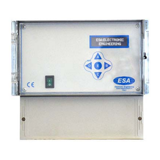
1.1 DESCRIPTION
Master unit for BUS SYSTEM for dedusting plant cleaning cycle control without dP control.
2.1 STANDARD FEATURES
A2a
Relay Voltage ON (K1)
B10b
Manual activation of every single output from keyboard
B1b
Select Number of outputs
B2x
Activation time from 0.05 to 5.00 sec.
B3x
Interval time from 1 to 999 sec.
B8a
Short-circuit protection of every single output
B9b
Electric control of output activation
C0
Input activation from external contacts
C4c
Cleaning cycle
C6a
ON/OFF cleaning cycle from external pressure switch. STOP at the end of the cycle
D14a
Operation hours-counter
D1a3
Additional cycles from voltfree contact. ALWAYS enabled.
D6a
ON/OFF cleaning cycle from external contact
G1
Maximum load power 25W per output
HVA
Input voltage selection
SL
Multi language display
Code:
Ex22DSR : ATEX - Zone 22
1
Max Nr. Output:
115 VAC - 230 VAC (24 VAC - 24 VDC On Request)
Voltage IN / OUT:
GENERIC DOCUMENTATION. THE SPECIFIC DOCUMENTATION IS ATTACHED TO THE SEQUENCER
MASTER UNITS BUS SYSTEM
II 3D Ex tc IIIC IP65 T100°C
Advertisement
Table of Contents

Related Manuals for ESA Ex22DSR


Summary of Contents for ESA Ex22DSR
- Page 1 Input voltage selection Multi language display II 3D Ex tc IIIC IP65 T100°C Code: Ex22DSR : ATEX - Zone 22 Max Nr. Output: 115 VAC - 230 VAC (24 VAC - 24 VDC On Request) Voltage IN / OUT: GENERIC DOCUMENTATION. THE SPECIFIC DOCUMENTATION IS ATTACHED TO THE SEQUENCER...
-
Page 2: Standard Features
2.2 STANDARD FEATURES Code Description Relay Voltage ON (K1) If the device is supplied, relay K1 is activated and the terminal board contact is closed. In case of power failure, this contact is open. B10b Manual activation of every single output from keyboard By keyboard, it is possible to activate manually and individually every single output for an operation test. - Page 3 2.2 STANDARD FEATURES Code Description ON/OFF cleaning cycle from external contact If contact D6a is open, the cleaning cycle is not enabled and the display shows 'START CONTACT D6a OPEN'. Close D6a to start cleaning cycle from the first electrovalve. NOTE D6a: Jump D6a if it is not used with inputs from external contact active (See Setup 5.1).
-
Page 4: Technical Features
3.1 INSTALLATION RULES AND SECURITY Protect the device against the direct exposure to the sun. Avoid arranging the device in the proximity of or in direct contact with any source of heat and electromagnetic field. Connect the device on supply lines different from those used for motor drives or other devices that may cause some noise on the net. - Page 5 5.1 ENTER DATA IN SET MODE SETUP / DISPLAY DESCRIPTION Range Code Default LANGUAGE SEL. Display language selection ENGLISH DIGITAL INPUTS ENABLE / DISABLE inputs from external contacts DISABLE PULSE TIME Pulse time from 0.05 to 5.00 sec. 0.01÷5.00 B2x 0.50 sec 0.50 sec.
- Page 6 6.1 DISPLAY INDICATIONS IN OPERATION DISPLAY DESCRIPTION Code 010 mg/m³ (A) TC Probe reading (xx mg/m³) TC Probe reading is option on request. START CONTACT Cycle stop since no remote start D6a OPEN Cycle stops waiting for fan start or dP under set fan threshold (See SET 11 section 5.1) VENTILATOR STOP Activation output solenoid valve 3...
- Page 7 7.1 DISPLAY INDICATIONS WITH ALARM DISPLAY DESCRIPTION Code OVERLOAD Overload alarm solenoid valves 3 ELECTROVALVE 003 ACT. FAILED Solenoid valve not activated - Solenoid valves 03 (option on request) B9x/B6x ELECTROVALVE 003 8.1 INFORMATION AND GUIDE ON THE DISPLAY 8.1 INFORMATION AND GUIDE ON THE DISPLAY Not available for this model...
-
Page 8: Wiring Diagram
9.1 WIRING DIAGRAM... - Page 9 10.1 ELECTRONIC BOARD SIZE AND VOLTAGE SETTINGS...
-
Page 10: Enclosure Dimensions
11.1 ENCLOSURE DIMENSIONS... -
Page 11: Warranty
12.1 PROBLEMS SOLUTIONS DEFECT POSSIBLE CAUSE SOLUTION Display OFF Fuse burnt. Check the protection fuse on supply line. Supply voltage. Check if supply voltage is present and if it agrees with supply voltage needed by the Jumper for input voltage selection device (clamps 1 and 2). - Page 12 Company name / Company name: ESA Electronic Engineering Postal address / Postal address: Via Kennedy, 28 Postcode and City / Postcode and City: 20010 Mesero (MI) Telephone / Telephone: +39 02 979 89 899 E-Mail address / E-Mail address: esa@esaelectronic.it...
- Page 13 II 3D Ex tc IIIC IP65 T100°C ADDITIONAL INSTALLATION RULES (ATEX ZONA 22) The ATEX certification decade in case of every type of modifications of the original device that are not done by the manifacturer All the electrical wiring must be done according to the Europen rule EN 60079-14 In case of faulty that does not depend only to the fuse, switch off immediately the supply voltage and contact the supplier.
Need help?
Do you have a question about the Ex22DSR and is the answer not in the manual?
Questions and answers