Advertisement
DOCUMENTATION INDEX
1.1
Description
2.1
Standard features (List)
2.2
Standard features (Details)
3.1
Installation rules and security
4.1
Technical features
5.1
Enter data in set mode
6.1
Display indications in operation
7.1
Information and guide on the display
8.1
Information and guide on the display
9.1
Wiring Diagram
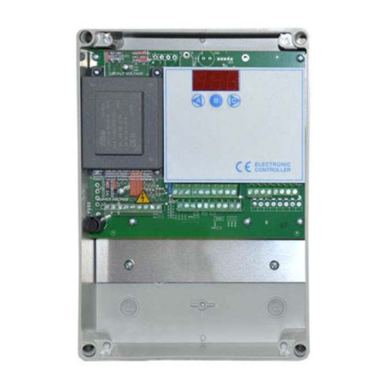
10.1
Electronic board size and voltage settings
11.1
Enclosure dimensions
12.1
Problems solutions
13.1
Warranty
14.1
Certificates
1.1 DESCRIPTION
Sequencer for dedusting plant cleaning cycle control without digital dP.
2.1 STANDARD FEATURES
B10b
Manual activation of every single output from keyboard
B1b
Select Number of outputs
B2x
Activation time from 0.05 to 5.00 sec.
B3x
Interval time from 1 to 999 sec.
B8b
Short-circuit protection of every single output
C0
Input activation from external contacts
C6
ON/OFF cleaning cycle from external pressure switch
D1a
Additional cycles after fan stop
D6
ON/OFF Cleaning cycle from external contact.
G1
Maximum load power 25W per output
HV
Input / Output voltage selection.
Code:
PB
32
Max Nr. Output:
115 VAC - 230 VAC (24 VAC - 24 VDC On Request)
Voltage IN / OUT:
GENERIC DOCUMENTATION. THE SPECIFIC DOCUMENTATION IS ATTACHED TO THE SEQUENCER
SEQUENCER FOR DEDUSTING PLANTS
Advertisement
Table of Contents

Related Manuals for ESA SEQUENCER FOR DEDUSTING PLANTS


Summary of Contents for ESA SEQUENCER FOR DEDUSTING PLANTS
- Page 1 SEQUENCER FOR DEDUSTING PLANTS DOCUMENTATION INDEX Description Standard features (List) Standard features (Details) Installation rules and security Technical features Enter data in set mode Display indications in operation Information and guide on the display Information and guide on the display Wiring Diagram 10.1...
-
Page 2: Standard Features
2.2 STANDARD FEATURES Code Description B10b Manual activation of every single output from keyboard By keyboard, it is possible to activate manually and individually every single output for an operation test. Press key C to select the desired output to be activated. Press key A to activate the output. The output is holded active for all the time that key A is pressed. -
Page 3: Technical Features
3.1 INSTALLATION RULES AND SECURITY Protect the device against the direct exposure to the sun. Avoid arranging the device in the proximity of or in direct contact with any source of heat and electromagnetic field. Connect the device on supply lines different from those used for motor drives or other devices that may cause some noise on the net. -
Page 4: Setup Description
5.1 ENTER DATA IN SET MODE (SETUP) 1. Press key C to have access to the SETUP menu F01 2. Press key C again to select the desired function F01, F02, F03 ... 3. Press key A to modify data. 4. - Page 5 6.1 DISPLAY INDICATIONS IN OPERATION DISPLAY DESCRIPTION Code Cycle stops for cleaning consent missing (D6 open) Cycle stops for ventilator OFF. Contact D1a open (See 2.2) Number of activated electrovalve Cycle stops for contact C6 open. (See 2.2) Additional cycles after ventilator stop active (Blinking points) Pause time between ev.
-
Page 6: Wiring Diagram
9.1 WIRING DIAGRAM... - Page 7 10.1 ELECTRONIC BOARD SIZE AND VOLTAGE SETTINGS...
-
Page 8: Enclosure Dimensions
11.1 ENCLOSURE DIMENSIONS... -
Page 9: Problems Solutions
12.1 PROBLEMS SOLUTIONS DEFECT POSSIBLE CAUSE SOLUTION Display OFF Fuse burnt. Check the protection fuse on supply line. Supply voltage. Check if supply voltage is present and if it agrees with supply voltage needed by the Jumper for input voltage selection device (clamps 1 and 2). - Page 10 Company name / Company name: ESA Electronic Engineering Postal address / Postal address: Via Kennedy, 28 Postcode and City / Postcode and City: 20010 Mesero (MI) Telephone / Telephone: +39 02 979 89 899 E-Mail address / E-Mail address: esa@esaelectronic.it...
Need help?
Do you have a question about the SEQUENCER FOR DEDUSTING PLANTS and is the answer not in the manual?
Questions and answers