Table of Contents
Advertisement
Quick Links
DOCUMENTATION INDEX
1.1
Description
2.1
Standard features (List)
2.2
Standard features (Details)
2.3
Option on request
3.1
Installation rules and security
4.1
Technical features
5.1
Enter data in set mode
6.1
Display indications in operation
7.1
Display indications with alarm
8.1
Information and guide on the display
9.1
Wiring Diagram
10.1
Electronic board size and voltage settings
11.1
Enclosure dimensions
12.1
Problems solutions
13.1
Warranty
14.1
Certificates
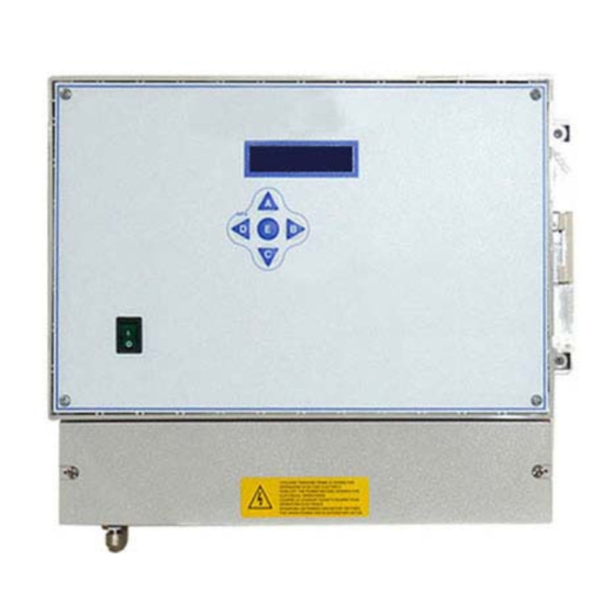
1.1 DESCRIPTION
Sequencer for dedusting plant cleaning cycle control with digital dP control by internal transducer.
2.1 STANDARD FEATURES
A1a
Minimum and maximum dP alarms on same relay (K2)
A2a
Relay Voltage ON (K1)
AL1
Alarm relay contacts open
B10
Manual activation of every single output from keyboard
B1b
Select Number of outputs
B2x
Activation time from 0.05 to 5.00 sec.
B3c
Interval time between ev. during post-cleaning
B3x
Interval time from 1 to 999 sec.
B8b
Short-circuit protection of every single output
C1
Digital differential pressure control (STOP at cycle end)
C13_10
dP full range 10.00 kPa = 100.0 mbar = 1012 mmH2O.
C4
Cleaning cycle
C4a
Automatic operation mode
C4b
Manual operation mode
C7c1
Minimum dP alarm. Contact open with alarm. Automatic reset.
C7d1
Maximum dP alarm. Contact open with alarm. Automatic reset.
C8
dP zero readout regulation
D14a
Operation hours-counter
D1b1
Additional post-cleaning cycles from dP readout. Activation at STOP.
D5a
Consent from external compressed air pressure switch
D6a
ON/OFF cleaning cycle from external contact
G1
Maximum load power 25W per output
HVB
Input and output voltage selection
SL
Multi language display
Code:
DC
32
Max Nr. Output:
115 VAC - 230 VAC (24 VAC - 24 VDC On Request)
Voltage IN / OUT:
GENERIC DOCUMENTATION. THE SPECIFIC DOCUMENTATION IS ATTACHED TO THE SEQUENCER
SEQUENCER FOR DEDUSTING PLANTS
Advertisement
Table of Contents

Related Manuals for ESA DC


Summary of Contents for ESA DC
- Page 1 SEQUENCER FOR DEDUSTING PLANTS DOCUMENTATION INDEX Description Standard features (List) Standard features (Details) Option on request Installation rules and security Technical features Enter data in set mode Display indications in operation Display indications with alarm Information and guide on the display Wiring Diagram 10.1 Electronic board size and voltage settings...
-
Page 2: Standard Features
2.2 STANDARD FEATURES The presence of options on request could nullify or modify the operating of standard features. Code Description Minimum and maximum dP alarms on same relay (K2) Minimum and maximum dP alarms act on the same relay. The display will specify the type of alarm. Relay Voltage ON (K1) If the device is supplied, relay K1 is activated and the terminal board contact is closed. - Page 3 JP2: Select the output voltage between 24, 115, 230 V (Only when the power supply is 115VAC or 230VAC). JP3: Select the output voltage between AC and DC only when JP2 is set to 24V. ATTENTION: set the same output voltage you have selected by means of the jumpers to adjust the trip threshold of the short-circuit.
- Page 4 2.3 OPTION ON REQUEST The presence of options on request could nullify or modify the operating of standard features. Code Description Emission control by TRIBO-CHECK probe. Alarms on relay K2. By connecting the Tribo-Check probe to the device it is possible to keep under control the dust emission in the duct. The TC probe management contain some function and possible alarm situations that allow to find if there is a broken bag or a continuos emission over a set threshold.
- Page 5 2.3 OPTION ON REQUEST The presence of options on request could nullify or modify the operating of standard features. Code Description Sensitivity for broken bag check If a bag is broken, whenever you activate the solenoid valve corresponding to this bag, this will produce a dust puff. The equipment can find out this failure and signal the row of bags where there is the breakage.
- Page 6 2.3 OPTION ON REQUEST The presence of options on request could nullify or modify the operating of standard features. Code Description D12c High emission alarm. If the readout of the TC signal is above the value in set up code D12 the high emission alarm will be activated. The display will show the alarm condition code E4 (see alarm description) and the relay will signal the alarm condition.
-
Page 7: Technical Features
3.1 INSTALLATION RULES AND SECURITY Protect the device against the direct exposure to the sun. Avoid arranging the device in the proximity of or in direct contact with any source of heat and electromagnetic field. Connect the device on supply lines different from those used for motor drives or other devices that may cause some noise on the net. - Page 8 5.1 ENTER DATA IN SET MODE SETUP / DISPLAY DESCRIPTION Range Code Default LANGUAGE SEL. Display language selection ENGLISH DIGITAL INPUTS ENABLE / DISABLE inputs from external contacts DISABLE OPERATION Operation Mode selection AUTOMATIC / MANUAL MANUAL PULSE TIME Pulse time from 0.05 to 5.00 sec. 0.05÷5.00 B2x 0.50 sec.
-
Page 9: Setup / Display
5.1 ENTER DATA IN SET MODE SETUP / DISPLAY DESCRIPTION Range Code Default MAX dP ALARM Maximum dP alarm threshold. 0.01÷9.99 C7d1 3.00 C7d1 3.00 kPa EV. VOLTAGE Threshold adjustment for option B8x correct operating. See jumper JP2 position. Vout = 24 V... - Page 10 5.1 ENTER DATA IN SET MODE SETUP / DISPLAY DESCRIPTION Range Code Default TC CONTROL Inclusion / exclusion TC probe control ZERO TC ADJ. TC reading zero adjustment. (TC reading on display) -9 ÷ +9 00 mg/m3 TC ADJUST. TC reading adjustment to get value on display in mg/m3 20 mA = 100 ALL.
- Page 11 7.1 DISPLAY INDICATIONS WITH ALARM DISPLAY DESCRIPTION Code OVERLOAD Overload alarm solenoid valves 3 ELECTROVALVE 003 ACT. FAILED Solenoid valve not activated - Solenoid valves 03 (option on request) B9x/B6x ELECTROVALVE 003...
- Page 12 5.1 ENTER DATA IN SET MODE SETUP / DISPLAY DESCRIPTION Range Code Default BROKEN BAG Alarm for broken bag check ev 3 ELECTROVALVE 003 EMISSION TC Continuous emission of dust above the set threshold D12c D12c OVER THRESHOLD PROBE SIGNAL TRIBO CHECK probe signal below 2 mA D12c D12c TRIBO <...
-
Page 13: Wiring Diagram
9.1 WIRING DIAGRAM... - Page 14 10.1 ELECTRONIC BOARD SIZE AND VOLTAGE SETTINGS...
-
Page 15: Enclosure Dimensions
11.1 ENCLOSURE DIMENSIONS... -
Page 16: Warranty
12.1 PROBLEMS SOLUTIONS DEFECT POSSIBLE CAUSE SOLUTION Display OFF Fuse burnt. Check the protection fuse on supply line. Supply voltage. Check if supply voltage is present and if it agrees with supply voltage needed by the Jumper for input voltage selection device (clamps 1 and 2). - Page 17 Company name / Company name: ESA Electronic Engineering Postal address / Postal address: Via Kennedy, 28 Postcode and City / Postcode and City: 20010 Mesero (MI) Telephone / Telephone: +39 02 972 89 899 E-Mail address / E-Mail address: esa@esaelectronic.it...
Need help?
Do you have a question about the DC and is the answer not in the manual?
Questions and answers