Table of Contents
Advertisement
Quick Links
Advertisement
Table of Contents

Related Manuals for Kowa AP-7000


Summary of Contents for Kowa AP-7000
- Page 1 INSTRUCTION MANUAL...
-
Page 3: Introduction
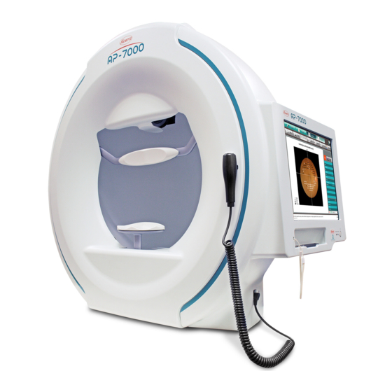
KOWA AP–7000 is an automatic perimeter intended for measurement of the visual field. This manual provides a description of the operating procedures of the KOWA AP–7000 and the precautions to be observed during its use. Please read this manual carefully to assure that the instrument can demonstrate its full capabilities and work safely. - Page 4 It may cause a fire, electrical shock, bodily injury, or instrument malfunctioning. Refer all servicing to Kowa or your Kowa dealer. Disassembly The instrument modified or repaired by anyone other than a Kowa designated repair facility prohibited will void the warranty.
- Page 5 Introduction Caution The power supply must be provided for the sole use of this instrument. Sharing the same power supply with other external devices may cause instrument malfunctioning. Be sure to prevent the instrument from being operated by anyone other than the following certified personnel: ・MD (Ophthalmologist), ophthalmology resident ・Nurse, vocational nurse...
-
Page 6: Meanings Of Symbols
Meanings of symbols... - Page 7 Introduction Symbol mark Symbol for “Type B applied part”. Symbol for “Power ON”. Symbol for “Power OFF”. Symbol for instrument status (Power ON or Standby) Symbol for “Response button jack” Symbol for “Reference the instruction manual” Symbol for “Pushing prohibited”. Symbol for “Warning”...
-
Page 8: Operating Precautions
Do not install any software other than the KOWA AP–7000 accessory software in this instrument. Otherwise, the instrument may be caused to malfunction. Kowa will not be liable for malfunction of the instrument caused by installation or execution of such extra software. -
Page 9: Precautions: Use Of Medical Electrical System
Any non – medical electrical equipment connected to this system to compose a medical system must comply with safety standards of IEC or ISO provisions applicable to such non – medical electrical equipment. Do not use any additional multi – tap or extension power supply cable other than those Kowa specified to this system. - Page 10 Combinations of medical electrical equipment and non–medical electrical equipment Precautions for system IEC 60601–1–1 “Safety requirements for medical electrical systems” describes the components combination grouped into various clinical settings. The brief overview of IEC 60601–1–1 is shown below. Medically used room Examples of Practical means Non-...
- Page 11 Introduction Medically used room Examples of Practical means Non- possible causes of compliance Inside the Outside the Situation No. medically for exceeding Apply 16.5 in all PATIENT PATIENT used room LEAKAGE situations ENVIRONMENT ENVIRONMENT CURRENT limits No causes of - No further 2a Items A and exceeding B are ME...
-
Page 12: Operational Considerations For Hospital Grade Electrical Instrument (Safety And Accident Prevention)
Clean and rearrange accessories, cables, etc. The instrument must be cleaned prior to use. 6. In case of a problem or malfunction, stop the operation and contact Kowa or your Kowa dealer for repair. 7. Instrument shall not be modified. -
Page 13: Components And Supplies
Introduction Components and supplies Main body:1 Power supply cable:1 Response button:1 Dust cover:1 Input pen:1 Projection lamp(Replacement):1 Fuses:2 Input pen – strap:1 Instruction manual:1 Head band2... -
Page 14: Table Of Contents
Contents Introduction ..................1 Safety precautions ................................1 Meanings of symbols ............................... 4 Operating precautions ..............................6 Precautions: use of medical electrical system ......................7 Operational considerations for hospital grade electrical instrument (safety and accident prevention) ................................10 Components and supplies ............................. 11 Contents .................... - Page 15 7.7. Scrollable display ..............................136 7.8. Sorting the examination results ........................137 8. Link with KOWA VK Series ............138 8.1. Automatic saving of perimetry results into Kowa VK Series ..............138 8.2. Simplifying the patient information input operation ..................139 8.3.
-
Page 16: System Description
(in time reduction mode), and manually – operated examinations. It is also available with Kowa’s original examination program that allows you to conduct perimetry in combination with a fundus image and check the correspondence between the perimetry result and the fundus image. -
Page 17: Name And Function Of Each Component
System description 1.4. Name and function of each component Main body Head rest Headband D o m e <Applied part> <Applied part> Describe inside the main body. Place the patient’s Stabilizes the head forehead against position of the patient. the head support, and ensure stability to prevent the face from moving. - Page 18 Display section [Input screen] Menu buttons [Setting] Sub-menu buttons Patient Eye fixation information monitor Chin rest move buttons Examination program Date and time Menu buttons [Setting] Open the corresponding screens: input screen, Allows you to make necessary settings. examination screen, result screen, and Appears in the same way on any screen.
- Page 19 System description [Examination screen] Examination program Corrective lens holder mark Examination point pattern display area Response button mark Examined eye Patient information Examination information Examination Gaze monitor status result display Examination point Stimulus presentation point Response button mark Stimulus presentation point Appears while the response button is being pushed.
- Page 20 [Result display screen] Examination result change buttons Examination program Result count button Examination result display area Examination program Shows the name of the examination program to be displayed. Examination result display area Shows the examination result and analysis result. Examination result change buttons Sequentially change the display of the examination result.
- Page 21 System description [Chronological change screen] Artifact button Reliability button Exception button Chronological change graph Examined eye and data information display area Chronological change graph and data display area Shows a chronological change graph and data. Examined eye information Shows examined eye information for chronological change. Artifact button Press to show a graph of examination result analysis indexes with artifacts considered.
-
Page 22: Installation
⑥ Insert the power supply cable to the power outlet. This instrument is floor–standing type (not intended for moving). When it is necessary to move the instrument, contact Kowa or your Kowa dealer. Example of installation Make sure the instrument is properly grounded to prevent bodily injuries. -
Page 23: Connecting An External Device
This instrument is provided with 2 USB connectors and an Ethernet connector as the external interface connector, allowing data output to a printer, media, and a personal computer. When it is necessary to install printer drivers for connecting a printer to the instrument, contact Kowa or your Kowa dealer where you purchased the instrument. -
Page 24: Flow Of Operations
Flow of operations Startup (P.24) Darken the room for examination. Set the power switch to ON (| side). Press the sub-power switch. Patient information input and examination program setup (P.27) Enter patient information (ID, name, date of birth, etc.). ... - Page 25 Press the sub-power switch. When the message “Do you wish to exit the KOWA AP-7000?” appears, select [OK]. Confirm that the power lamp is lit in orange (STANDBY), and then set the power switch to OFF. When ending the examination, be sure to follow the procedure described in “4.1 Switching on and off the instrument”.
-
Page 26: Preparation For Examinations
Preparation for examinations 4.1. Switching on and off the instrument How to start the instrument 1. Confirm that the surrounding area of the instrument is dark enough to perform an exanimation. 2. If any peripheral device such as a printer is connected to the instrument, set its power to ON. - Page 27 Preparation for examinations Since the chin rest automatically operates for initialization, do not touch Caution the chin rest or the exterior on the front. Otherwise, it may cause injury. Prohibitory...
- Page 28 How to stop the instrument 1. Press the sub power switch (which does not respond on the examination screen). 2. When the finish message “Do you wish to exit the KOWA AP-7000?” appears, select [OK]. Sub-power switch 3. Approximately 20 seconds later, the screen enters the state without any data displayed (black screen).
-
Page 29: Operations Available With The Input Screen
Preparation for examinations 4.2. Operations available with the input screen Upon startup of the instrument, the input screen is automatically opened. The input screen also appears when the menu button [Input] is pressed on another screen. The input screen allows you to make preparations for an examination including patient information input and examination program selection. -
Page 30: Loading Patient Information By [Open List]
4.3. Loading patient information by [Open List] When you press [Open] on the input screen, the patient ID list dialog appears. In the patient ID list dialog, [Patient ID list] is selected as the default. The patient ID list shows a list of ID information of the patients that have been examined so far. - Page 31 Preparation for examinations You can press [Export] in the patient ID list dialog to export all examination results of the selected patient or selected examination results. You can set the export destination, file format, file name, and content of the examination result using the procedures in “4.10 Configuration settings.”...
-
Page 32: Patient Information Input
4.4. Patient information input Input information of patients. The input information consists of the following items: Patient information (ID, Name, Correction, Sex, Doctor, Visual Acuity, Diagnosis, Pupil Diameter, Eye pressure, Comment, Drug Administration) Program Parameter When you select a text box on the input screen, the corresponding input dialog appears. - Page 33 Preparation for examinations When you press [Resistration list Delete], the entry list deletion dialog appears. It allows you to select and delete items from the lists of doctors, diagnosis, comments, and drug administrations. When you select an item and press [Delete], a confirmation message dappears.
- Page 34 4.4.1. ID (Value) If you select “ID” in the Configuration dialog and set “Input” to “Value,” the ID input dialog appears when you select the ID text box on the input screen. You can input an ID using up to 32 characters. Use the keyboard in the dialog to input the ID.
- Page 35 Preparation for examinations 4.4.3. Date of birth When you press the Day, Month, or Year input box for Date of Birth, the corresponding input dialog appears. The selected item (Day, Month, and/or Year) is shown in Orange. You can input a value using the numeric keys in the dialog.
- Page 36 4.4.4. Correction When you press the Correction text box, the correction input dialog appears. An examination at a point within central 30° requires near correction at a distance of dome diameter 30 cm. This input dialog allows you to input a near correction value for performing the examination at a point within central 30°. You can directly input a numeric value.
- Page 37 Preparation for examinations Calculating near correction value from distant correction value This function should be used to calculate a near correction value by inputting a distant correction value in “ 2 Inputting correction values” above when a lens is used. If the date of birth is entered, [Distant >>...
- Page 38 4.4.5. Doctor When you press the Doctor input box in patient information input dialog 2, the doctor input dialog appears. You can input a doctor’s name using up to 32 characters. The input method is the same as that of the name. When you press [Register], the input doctor is entered to the doctor list.
- Page 39 Preparation for examinations 4.4.10. Comment When you press the Comment text box in patient information input 2dialog, the comment input dialog appears. You can enter a comment using up to 128 characters. The input method is the same as that of the name. When you press [Register], the comment is registered in the comment list.
-
Page 40: Loading Patient Information From The Advance Entry List
4.5. Loading patient information from the advance entry list If any information registered through the patient information input dialog is available, you can load patient information from the advance entry list. (For how to register information through the patient information input dialog, see P. 30.) Press [Registration List] on the input screen, and the advance entry list appears. -
Page 41: Clearing The Patient Information
Preparation for examinations 4.6. Clearing the patient information Pressing [Clear Data] with patient information input allows you to clear the patient information. When you press [Clear Data], the clear confirmation message appears. When you press [OK], the patient information on the input screen is cleared. When you press [Cancel], the confirmation message dialog closes to return to the input screen. -
Page 42: Setting Of Examination Program And Examination Parameter
4.7. Setting of Examination Program and Examination Parameter Use the input screen to set an examination program and examination parameters. You can select any of the examination programs shown in the table below. You can change the parameter values for each examination program. When you press [Program], the program selection diagram appears. - Page 43 Preparation for examinations 4.7.1. Examination program setting The program selection dialog allows you to change the settings for examination programs. The examination points (right eye) and parameters for the selected program are shown on the right side of the dialog. When you press [OK] after completing the program setting through [Registration list] or [Program list], the new settings are shown on the input screen.
- Page 44 When you press [OK] in the program change dialog, the program name change dialog appears. This dialog allows you to change the program name. You can enter a new program name using up to 16 characters. When you press [OK], the program name change is reflected in the program selection dialog.
- Page 45 Preparation for examinations 4.7.2. Examination parameter setting [Common parameters] In the description below, the values provided with the asterisk mark () are set by default. You can change those parameter values using the parameter value change dialog when necessary. ① Presentation time ...
- Page 46 ⑬ AP–340 When you press this button, the size, presentation time, and color of the stimulus are set to those which most closely approximate the settings in automatic perimeters KOWA AP-340 and AP-125. 【Screening / Supra Parameter】 The values provided with the asterisk mark () are set by default for screening.
-
Page 47: Each Examination Program
Preparation for examinations 4.8. Each Examination Program 4.8.1. Screening The screening examination programs include Standard, Precision, Center, Periphery, Glaucoma, Hemianopia, Center #1, and Center #2. Since each program is provided with the quick mode except for Center #1 and Center #2 programs, 14 programs are available for screening examinations. - Page 48 Examination method The Screening examination adopts the method of dividing the sensitivity of a patient at each point into two or more steps (zones). The number of zones can be selected from 2, 3, and 4. The presented stimulus intensity for dividing the sensitivity into zones varies with the setting of the reference value (5 dB or p–value) (See the table below).
- Page 49 Preparation for examinations ※ Normal Sensitivity Curve The normal sensitivity curve is a visual field map of a person with a normal visual field. The sensitivity differs in individuals and by ages in people, however, the sensitivity distribution (the shape of a visual field) is almost the same.
- Page 50 4.8.2. Supra There are 6 kinds of examination programs, Standard・Macula・Mariotte・Optional・D–Test・Esterman Both Supra Examination Program Examination Program Examination Area and Points Summary Time [min.] Within 60° 83 points Standard 3 to 5 General Group examination (Glaucoma exam, etc.) Macula Within 10° 21 points 1 to 2 Abnormal visual field in the macular area...
- Page 51 Preparation for examinations About Esterman Both When the Esterman Both examination program is used, examinations are performed with the chin rest moved fully to the right and the face placed on the left portion of the chin rest. Any corrective lens is not used. If a patient wears glasses daily, perform examinations with the glasses on.
- Page 52 ② 4.8.3. Threshold There are 6 kinds of examination programs, Center 1, Center 2, Meridian, Macula 1, Macula 2, and Periphery Threshold Examination Program Examination Program Examination Area and Points Summary Time [min.] Center 1 8 to 14 Quick 1 6 to 8 General, Glaucoma, Regional Within 30°...
- Page 53 Preparation for examinations Examination method An examination is performed by making measurements up to the threshold of each examination point with the varied intensity of the stimulus. For the Meridian threshold examination, a meridian to be examined is first selected. When you select Macula, the fixation target is automatically set to the 4 points at the lower center.
- Page 54 Is o p t e r There are 4 types of programs: the program to examine the isopter only and the programs combined with Screening Center, Screening Center #1, and Threshold Center #1, respectively, to examine the peripheral field and center field at the same time.
- Page 55 Preparation for examinations Examination method A stimulus with the single intensity is moved along the meridian. The points with responses from the patient are connected to grasp the shape of the patient’s visual field as an isopter. Parameter setting You can set the following parameters: False–positive reaction, False–negative reaction, Stimulus color, Background color, Fixation Target, AP–340 Isopter setting When you select Isopter in the Program Change dialog, [Isopter] in the...
- Page 56 ⑥ Shift The default is “OFF.” When there are two or more isopters and you set “Shift” to “ON,” the examination start direction is shifted by the angle half the interval for each isopter and the same examination start direction is set for every other isopter.
- Page 57 Preparation for examinations Stimulus registration method i. Select the type of the start point to register: Start 1 or Start 2. (Start 2 can be selected only if “Blind spot” is set in Start 2.) ii. Select the intermediate filter (a, b, c, d, or e), intensity (1, 2, 3, or 4), and size (I, II, IV, or V) of the stimulus to be registered.
- Page 58 4.8.4. Custom There are 7 kinds of examination programs, Circle threshold, 1 point Threshold, Quadrant threshold, Optional threshold ○, Optional threshold#, Optional Screening ○, Optional Screening #. The programs provided with symbol ○ or # in their names allow you to select the position of the examination points. Each symbol shows the point arrangement of the stimulus to be selected.
-
Page 59: Perimetry Examination Fundus Images
Preparation for examinations 4.9. Perimetry examination with fundus images In perimetry examination with fundus images, the visual field is examined with a fundus image displayed on the screen. By overlapping the fundus image and the perimetry result, you can grasp the correspondence between the two. The understanding of whether the abnormal development of the two corresponds with each other or the abnormality of which one precedes the other will help to make the diagnosis. - Page 60 You can make settings for fundus images as shown below. When you select an examination program with the perimetry examination fundus images available and press [Fundus] on the input screen, the file selection dialog appears as shown below. Example of fundus image file selection dialog When you select a fundus image file to be used, a fundus image appears.
-
Page 61: Configuration Settings
Preparation for examinations 4.10. Configuration settings When you press [Setting], the Configuration dialog appears. You can make various settings in this dialog. [Setting] is not available during examination. Configuration dialog When you press [OK] in the Configuration dialog upon completion of settings, the new settings are reflected. When you press [Cancel], the dialog is closed without any settings changed. - Page 62 The default is “1” Normal eye database Select the normal eye database to be used for analyzing and displaying the measurement results on other perimeter such as KOWA AP–6000. The default is “AP–7000” AP–7000 Regardless of the model on which measurement was made, analysis is executed with the normal eye database of KOWA AP–7000.
- Page 63 Preparation for examinations For the items shown below, when you press the applicable button, the corresponding dialog appears. When you press [OK] upon completion of the item setting, the dialog is closed. Then, press [OK] in the Configuration dialog, and the new setting is reflected. When you press [Cancel] the dialog is closed with the setting unchanged.
- Page 64 Mark You can change the screening mark and grayscale mark. Screening [ 1 ] Kowa automatic perimeter “KOWA AP–3000” and “KOWA AP–5000” (earlier version) [ 2 ] Standard setting Scale [1] Kowa automatic perimeter “KOWA AP–5000” (later version)and “KOWA AP–6000” (earlier version) [2]...
- Page 65 Preparation for examinations Chronological changes You can select two graphs to display chronological changes from the following 12 items. MD [Center] PSD [Macula] Quadrant TD [Macula] PSD [Center] AGIS Classification CIGTS Anderson MD [Macula] Quadrant TD [Center] Boxplot With Graph3,4 set to [ON], you can add other two graphs to display chronological changes. You can select the items from the 12 items above.
- Page 66 Specify the data drive. Database Select the database type. When the KOWA VK database is MSDE, you need to set an SQL server. If you select [MSDE], set the server name and server type. Press [VK Write] to execute data write to KOWA VK.
- Page 67 ① Browsing the results of examinations executed on KOWA AP–7000 from another manufacturer’s filing system KOWA AP–7000 outputs an examination result file (images and text) to the link destination upon completion of the examination. Reading the output file from the other manufacturer’s filing system enables the examination results of KOWA AP–7000 to be browsed in that filing system.
- Page 68 ※ Patient information file in (2) above The file name is ap5.tmp. The file content is [“ID,” ”Name,” ”Date of birth”]. The content of each item is the same as that in the text file of the examination result file in (1). Voices and buzzers.
- Page 69 Preparation for examinations The early stage Threshold You can set the initial display format of threshold examination results. For details about f the format, see “6.6 Analysis of Threshold Examination Result”. Color allows you to set the grayscale display to “Gray” or “Color.” With “Quick1 after the second times”...
- Page 70 Date You can set the date and specify the display format of the date and time. Combination with database You can combine a database stored on another Kowa automatic perimeter. Select the file folder of the database to be combined.
- Page 71 Preparation for examinations Check the intensity You can specify whether to enable or disable the intensity check on the examination screen and the yellow background intensity check during startup. If you set Background [Yellow] to “OFF,” you cannot set the background for examinations to “Yellow.” You can make settings for ID input.
- Page 72 Safely Remove Hardware A list of devices connected to the USB connector is shown. Press [Refresh] to update the device list. When you press the row of the device you wish to remove, the row is selected and shown in orange. Then, you can press [Stop] to safely remove the selected device.
-
Page 73: Preparation For Patients And Alignment Of Examined Eyes
Preparation for examinations 4.11. Preparation for patients and alignment of examined eyes After entering the patient information, setting the examination program and parameters, and positioning the corrective lens in the holder if needed, prepare the patient for the examination. 4.11.1. Setting a corrective lens Set a corrective lens adjusted for the eye to be examined. - Page 74 4.11.2. Explanation for patients First, provide a relevant explanation about the examination to a patient. The patient’s comprehension of the examination influences the reliability of the examination result. Tell the patients the following matters especially. An examination is performed in a dark room, one eye is examined at a time. The eye not to be examined is covered.
- Page 75 Preparation for examinations 4.11.4. Alignment of an Eye to be examined After preparing the patient for the examination, align the position of the examined eye. Make sure that the chin rest and head rest are cleaned. If a corrective lens is required, be sure to set it in the corrective lens holder before the patient places his/her chin on the chin rest.
-
Page 76: Examination
Examination 5.1. Operations available with the examination screen When you press [Test] in the menu button area after completion of settings and preparations, the examination screen appears. The examination screen allows you to perform the operation from the examination start to the examination completion. Examination screen (before examination start) Examination screen (during examination) - Page 77 Examination The examination screen allows you to perform the following operations. Turns ON when a selection program of examination point is executed. Allow a patient to practice before an examination is started. (P.76 5.2.1 Practice) Start an examination. Resume the currently interrupted examination. Temporarily interrupt the current examination.
-
Page 78: Operational Procedure In Examination
5.2. Operational procedure in examination The operation flow of the examination from start to completion is as shown after “5.2.1 Practice.” In the following examination programs, it is necessary to select examination points before starting the examination. Threshold – Meridian Supra –... - Page 79 Examination 5.2.2. Examination Start When you press [Start] after the patient adapts to the luminance in the dome (guideline: 1 to 2 min. after the patient is seated in front of the dome), the pre–exam setting is performed as described below, and then, the examination starts. Gaze monitor setting If the gaze monitor function (P.
- Page 80 Blind spot position setting If the fixation loss is set to ON in the applicable parameter setting, setting the blind spot for the patient can be performed. The blind spot position setting will be required to confirm the fixation loss. (P. 96) The blind spot position setting is not executed in the 1 point threshold examination and isopter examination.
- Page 81 Examination 5.2.3. During Examination After the examination has started, occasionally check the eye fixation monitor to see whether the patient is gazing at the center of the dome. If the examined eye becomes out of place, move the chin rest and align the pupil’s center of the examined eye with the center of the white cross-hairs on the eye fixation monitor.
- Page 82 When using a corrective lens and the examination point is within central 30° and more than 30° from the center, the area within central 30° is examined first. After finishing the area within 30°, the examination stops and a dialog stating, “Put back the lens frame.”...
-
Page 83: Programs Requiring Examination Point Selection
Examination 5.3. Programs requiring examination point selection The following examination programs require examination points to be selected before the examination starts. 5.3.1. Threshold – Meridian examination The examination point selection screen for the Threshold – Meridian examination is as follows. Select the meridian to examine, and press [Start]. - Page 84 5.3.2. Custom–Circle Threshold examination The examination point selection screen for the Custom–Circle threshold examination is as follows. Select the circle to examine, and press [Start]. During the examination, the examination result screen graphically shows a distribution of the threshold values on the selected circumference of circle.
- Page 85 Examination 5.3.3. Quadrant Threshold examination The examination point selection screen for the quadrant threshold examination is as shown below. Select the quadrant to examine, and press [Start]. You cannot select two or more quadrants. If you select the second quadrant, the already selected quadrant is deselected. Before Quadrant Threshold examination...
- Page 86 5.3.4. Optional examination The following examinations allow you to arbitrarily select examination points. Supra–Optional Custom–Optional threshold○ Custom–Optional threshold# Custom–Optional screening○ Custom–Optional screening# Supra–Optional (Custom–Optional threshold, and ○Custom–Optional screening ○: Same arrangement) Custom–Optional threshold# (Custom–Optional screening #: Same arrangement)
- Page 87 Examination You can make selections by a rectangular tool or lariat tool. The rectangular tool is effective to select all the stimuli in a certain area. The lariat tool is effective to finely select the stimulus. Both can choose two or more areas. Rectangular tool procedure ①...
- Page 88 lariat tool procedure ① ① Select [Lariat]. ② Touch the start point. ③ While touching, move the input pen. ④ Release the input pen. ⑤ Press [OK]. ③ ④ ⑤ ② ⑥ The selected points are shown ●. Use the same procedure to select the already selected points, press [Delete] in the dialog, and press [OK], and the already selected examination points are deselected.
- Page 89 Examination 5.3.5. Fundus perimetry When you press [Test] after selecting the fundus image on the input screen (P. 57), the operation proceeds to the coordinate setting on the fundus image and the examination point selection, in this order. The coordinate setting and examination point selection are performed in the following procedure. ④...
-
Page 90: Manual Examination
5.4. Manual examination 5.4.1. 1 point threshold examination Point being examined Intensity adjustment buttons Point examined already 1 point threshold examination The examination is executed in the following procedure. ① Press the button of a point to be examined. ② The examination point enters the selected state. In the dome, a stimulus with an intensity of 50 dB is presented at the point. - Page 91 Examination 5.4.2. Isopter examination (Manual) Examination:Manual The manual examination of the isopter examination is executed as described below. Prior to specifying the examination point, select the intensity, size, and speed of the stimulus. Delete button Intensity/ Size selection Stimulus speed selection Stimulus moving method selection...
- Page 92 Up to 5 isopters can be examined including the automatic examination. If you try to perform the examination with the 6th stimulus, the following message appears, disabling the examination. Max. Number of isopters ① Moving method: “Start + Direction” Press [Start + Direction] to set the stimulus moving method. Touch the examination start position.
- Page 93 Examination ② Moving method: “Start + Goal” Press [Start + Goal] to set the stimulus moving method. Touch the examination start position. Then, select one point (goal) in the moving direction. If you have selected [Center/Goal] for the goal position setting in the Isopter dialog, the stimulus stops at the goal. If you have selected [Maximum], the stimulus passes through the goal to move to the maximum range available for the examination until the examination in the current direction finishes.
- Page 95 Examination If you activate deletion of the examination result during manual examination of auto + manual examination, the examination results which cannot be deleted (the results of automatic examination) are grayed out. In case the [Delete] button is activated during manual examination of auto + manual examination ④...
- Page 96 Lines which are connected as an isopter are only for stimuli with which a manual examination has been executed. Select the specified stimulus points in order of connection. When a connected line becomes a closed curve, it is fixed as the examination result. If you press [OK] according to the number of unconnected point, the line is fixed as the examination result.
-
Page 97: Fovea Threshold Examination (Fovea Examination)
Examination 5.5. Fovea threshold examination (Fovea examination) In 3 examinations of Threshold – Center 1, Threshold – Center 2, and Isopter + Threshold, the fovea examination can be carried out. If you set the fovea examination to ON during program selection, the fovea examination is performed in the following procedure when the threshold examination is started. -
Page 98: Examination Reliability
5.8. Examination Reliability The reliability of an examination can be tested by 3 indices below. 5.8.1. Fixation Loss (Heijl-Krakau Method, H-K Method) When the blind spot is being stimulated, the characters of “Fixation loss” are shown in orange in the lower right of the examination screen. -
Page 99: Display, Print, And Analysis Of Examination Results
Display, Print, and Analysis of Examination Results Display, Print, and Analysis of Examination Results 6.1. Operation available with the result screen Upon completion of the examination, the display automatically switches to the examination result display screen. If you use [Open] to load a past examination result or if you press the menu button [Result] when entering the patient information containing the saved examination result, the display is switched to the examination result display screen and the most recent examination result is shown on the screen. - Page 100 The examination result screen allows you to perform the following operations: Load the patient information and past examination results from the patient ID list. (P.28 4.3 Loading patient information by [Open List]) Print the examination results. (P.100 6.3 Print) Display the examination results of both eyes side by side on the screen. (P.101 6.4 Both eyes) Display the examination results with the same ID in multi –...
-
Page 101: Examination Result Switchover And List Display
Display, Print, and Analysis of Examination Results 6.2. Examination result switchover and list display The [Examination result switchover] button and [Result count] button (Order of displayed results/Total of results) are displayed above the patient information on the right of the examination result screen. Press [Review] to display the previous examination result of the patient with the same ID or press [View] to display the next examination result. -
Page 102: Print
6.3. Print If a printer (available separately) is connected to this instrument, you can print an examination result. For details on the printer connection, see “2.2 connecting an external device”. When you press [Print] in the upper left of the screen, the specified examination result is printed. The printout is as shown in the diagram below. -
Page 103: Both Eyes
Display, Print, and Analysis of Examination Results 6.4. Both eyes If both eyes of the same ID are examined on the same day, or examined before with the same program, you can display the results of the eyes side-by-side by pressing [Combination]. [Combination] becomes active when an examination result of an eye satisfying the previously mentioned conditions is available in addition to the examination result of an eye being displayed,. - Page 104 Combine the examination results of both eyes If the examination parameters for both eyes to be displayed are the same, you can combine the examination results of both eyes. Example of the combined result Press [Combination] to display the combined result as shown above. Press [Print] to print the combined result.
- Page 105 Display, Print, and Analysis of Examination Results The examination results are combined in the following method. Threshold For the examination points common to both eyes, the examination results of the more sensitive eye are adopted. Left Right Combined result Screening For the examination points available only for either one eye, the examination results with those points available are adopted.
-
Page 106: Multi
6.5. Multi You can press [Multi] to divide the screen into a maximum of 4 display areas and show a different examination result of the same ID in each display area. The examination results are chronologically displayed in the upper left, upper right, lower left, and lower right in this order. - Page 107 Display, Print, and Analysis of Examination Results 6.5.1. Comparing examination results The multi – display screen allows you to compare 2 examination results of the same program for the same eye. Comparing examination results display The comparison result and 2 examination results to be compared are chronologically displayed on the left and right sides of the comparison screen, respectively.
- Page 108 Use the following procedure to compare the examination results: ① Press [Comparison]. ② The examination result numbers available for the comparison are shown in green. Those unavailable for the comparison are grayed out. Select the first examination result. The color of the selected examination result number turns orange. To cancel the selected examination result, select it again.
- Page 109 Display, Print, and Analysis of Examination Results Comparing Screening examination and Supra examination results The description of the marks displayed at each point on the comparison display is as follows: ○:The sensitivity is better than the previous examination results. ・:The sensitivity has not changed compared to the previous examination results. ●:The sensitivity is lower than the previous examination results.
- Page 110 6.5.2. Combine the examination results For the examination results of the same eye with the same ID, you can combine the central visual field examination result and peripheral visual field examination result or the central visual field examination result and isopter examination result to grasp the whole visual field.
-
Page 111: Analysis Of Threshold Examination Result
○ ○ ○ * For Threshold – Macula 1 and Threshold – Periphery Kowa pack 1, the threshold, scale, total deviation, and Bebie curve are displayed. You can press [Print] to print the currently displayed examination result. For analysis of the result of an interrupted examination, only Value and Scale are available. - Page 112 The list of Threshold–Center1 examination results is shown below. Value + Scale is Threshold–Periphery examination results. Numeric displayed Kowa pack 1 (Gray)※Threshold – Periphery Scale (Gray) Scale (Color) 3D (Gray) 3D (Color)
- Page 113 Display, Print, and Analysis of Examination Results Kowa pack 1 (Gray) Kowa pack 2 (Color)
- Page 114 Total value of Mariotte blind spot Program name Analyze method each quadrant ② Bebie curve Scale Threshold ① Total value of whole Analysis Reliability Total deviation Total deviation p-value Meaning of p-value mark Gaze monitor All (Gray) Pattern deviation Correspondence of Pattern deviation p-value color / gray of Scale to Threshold Value...
- Page 115 Display, Print, and Analysis of Examination Results 6.6.1. Threshold The measured sensitivity [dB] of each point is displayed. The higher the value, the higher the sensitivity, which means the patient can see a stimulus of lower intensity. For example, the patient was able to see the stimulus of 28dB at the point of ① of the upper center, and 30dB at ② of the upper center.
- Page 116 6.6.5. Pattern deviation The difference between the measured sensitivity curve and the normal sensitivity curve is displayed. The local visual field defect can be shown clearly. The normal visual field pattern of the patient’s sensitivity is estimated, and the difference between the measured threshold at each point and the estimated visual field pattern is shown.
- Page 117 Display, Print, and Analysis of Examination Results 6.6.7. MD (Mean Deviation) MD refers to an average value of the total deviation. Overall average visual field defect is displayed. When the value is negative, or the value is less, the visual field is lower than the normal sensitivity curve. The p-value is the provability variable showing the degree of abnormality of MD.
- Page 118 6.6.10. Anderson’s Criteria When one or more of the three criteria in the table below are satisfied, the symptom is judged as an early glaucomatous visual field defect. On the screen, a satisfying item is shown on an orange background while an unsatisfying item is shown on a white background.
- Page 119 Display, Print, and Analysis of Examination Results 6.6.14. VFI (Visual Field Index) The VFI is an index which is conscious of patient’s QOV (Quality of Vision) and shown in units of percentage. It is 100% when the visual field is normal; it is 0% when the visual field is completely lost. The pattern deviation p–value (total deviation p–value when MD is –20dB or less) is used to show the result of each examination point in the range of 0 to 100%, weight for each examination point, and then calculate the score into a VFI value.
-
Page 120: Fundus Perimetry Examination Result Display
Fundus perimetry examination result display An enlargement function is provided for displaying fundus perimetry examination results. It allows a section of the examination result image to be enlarged. Use the following procedure: ① Press [Enlarge]. While keeping it in contact with the screen, move the input pen to specify the range of enlargement. ②... -
Page 121: Isopter Examination Result Display
Display, Print, and Analysis of Examination Results 6.8. Isopter examination result display The result display of the Isopter – Standard examination is provided with the “Paint out Scotoma” function and the “Enlarge” function. 6.8.1. Paint out Scotoma This function allows you to paint out the closed curve of the examination results using the color of the stimulus. The procedure is as follows. - Page 122 6.8.2. Enlarge You can press [Enlarge] to enlarge the central area (up to the displayed visual angle of 30°). When you press [Enlarge] during enlarged display, the screen returns to the previous display mode. Enlarge of the Isopter examination...
-
Page 123: Re-Test
Display, Print, and Analysis of Examination Results 6.9. Re–Test You can perform the same examination as one which is currently showing on the screen. When you press [Re-Test] during display of the examination result, the re–test selection dialog box appears. Re–test selection dialog box There are 2 types of re–test. - Page 124 6.9.2. Re–test of each point When you press an examination point displayed in the re–test selection dialog box, the point is selected and enclosed by an orange circle. To deselect the selected point, press the point again. The point is deselected and the red circuit disappears. When you press [Remove selection], all the selected points are deselected at one time.
- Page 125 Display, Print, and Analysis of Examination Results For the isopter examination, re–test of each point is available for the examination of which result was obtained automatically. Regardless of the Auto + Manual and Auto examinations, re–test of each point is carried out with the Auto + Manual examination program.
-
Page 126: Editing Of Patient Information
6.10. Editing of patient information When you press [Edit Date], the patient information editing dialog appears as shown in the diagram below. This dialog allows you to edit the patient information for the examination result currently displayed on the screen. The updated name, date of birth, and sex are applied to all examination results with the same ID. - Page 127 Display, Print, and Analysis of Examination Results MEMO...
-
Page 128: Chronological Change
Chronological change 7.1. Operations available with the chronological change screen The chronological change screen enables the examination result analysis indexes to be graphically displayed as chronological data. This facilitates you to grasp the chronological changes of examined eyes. In addition, the results of the examination result analysis can be displayed in chronological order. When the following conditions are met, the chronological changes can be displayed: Date of birth is input. - Page 129 Chronological change The chronological change screen allows you to perform the following operations. Print the chronological change in graph form. (P.128 7.2 Print) Toggle between graphic display and data display. (P.133 7.4 Data display) Change the eye of which data is displayed. (P.134 7.5 Changing over the examined eye for display) Emphasize an arbitrary period of time.
-
Page 130: Print
7.2. Print When a printer (separately available) is currently connected, the chronological change being displayed can be printed. For the connection with a printer, see “2.2 connecting an external device.” When you press [Print] in the upper left of the screen, the chronological change being displayed is printed. The printout is as shown in the diagram below. -
Page 131: Graph Displays
Chronological change 7.3. Graph displays The chronological change screen displays two different graphs with the following 12 analysis indexes per screen at the same time. You can select which graphs to display by pressing [Setting] and [Chart] (P. 62) When Graph3,4 is set to [ON] in the Chart dialog, two other graphs can be added to display chronological changes. Graph3 and Graph4 are shown when you press [Switch graph] during display of Graph1 and Graph2 MD[Center] PSD[Macula]... - Page 132 MD [Center] and MD [Macula] The MD [Center] and MD [Macula] graphs show the chronological change graph and MD forecast as illustrated in the diagram above. The chronological change graph shows the MD value, p=5%, and p=1% by using a dashed line. The area below Caution MD is shown in yellow.
- Page 133 Chronological change PSD [Center] and PSD [Macula] The PSD [Center] and PSD [Macula] graphs are as shown above. In the graphs, the PSD value 0, p=5%, and p=1% are shown by dashed lines. V F I In the VFI graph, the chronological change and VFI forecast are shown as in the diagram above. In addition, the linear regression and VFI forecast are also shown in the same way as MD.
- Page 134 Quadrant TD [Center], Quadrant TD [Macula] The graphs of quadrant TD [Center] and quadrant TD [Macula] are as shown above. Stage, Anderson The Stage and Anderson graph are as shown above. The vertical axis indicates each score. The Anderson graph is classified into three stages of Early, Moderate, and Severe from the top in this order.
-
Page 135: Data Display
Chronological change 7.4. Data display You can press [Switch graph] to toggle between graph display mode and data display mode. In the data display mode, the examination information, scale, threshold, total deviation p–value, pattern deviation p– value, and Bebie curve of each examination result are arranged in a vertical row and displayed in chronological order. This display method allows you to easily grasp the change of each information item. -
Page 136: Changing Over The Examined Eye For Display
7.5. Changing over the examined eye for display You can press [Switch eye] to change over the examined eye for displaying the graphs and data. Each time you press [Switch eye], the examined eye for display is changed in the order of (Both eyes) →... -
Page 137: Graph Emphasizing
Chronological change 7.6. Graph emphasizing In the graph display mode, data in a specified period of time can be emphasized. In particular, the MD [Center], MD [Macula], and VFI graphs allow you to specify a period of time and highlight the linear regression in the specified period. This function is useful, for example, when checking whether the changed treatment is effective or not. -
Page 138: Scrollable Display
7.7. Scrollable display You can press [Scroll] to toggle between single – page display mode and scrollable display mode. The scrollable display mode allows you to change the display range by sliding the scroll bar in the lower portion of the screen. -
Page 139: Sorting The Examination Results
Chronological change 7.8. Sorting the examination results You can sort the results based on the artifact and reliability index during the graphic display of the chronological change. When you press [Artifact], it turns on and the graph of the examination result analysis index with the artifact is taken into consideration. -
Page 140: Link With Kowa Vk Series
This instrument can perform the following functions by linking up with KOWA filing system “VK Series.” For changing the settings to link up with KOWA VK Series, contact Kowa or your Kowa dealer. 8.1. Automatic saving of perimetry results into Kowa... -
Page 141: Simplifying The Patient Information Input Operation
ID input In the ID input dialog, enter the patient ID which does not exist in KOWA AP–7000 but exists in KOWA VK Series. Press [OK], and then, the patient information (ID, name, date of birth, and sex) corresponding to the input ID is read and enters the input state. -
Page 142: Maintenance And Inspection
9.2. Daily inspection (Inspection items for the user) Inspect this instrument in accordance with “KOWA AP–7000 daily inspection table” below. If any abnormality is found during daily inspection and cannot be solved by the maintenance described in this document, contact Kowa or your Kowa dealer for specific detail. -
Page 143: Regular Inspection (Maintenance Inspection Items For The Vendor)
(Maintenance inspection items for the vendor) In order to use this instrument safely over its useful life, we recommend you to have it inspected annually. For the content and cost of the inspection, contact Kowa or your Kowa dealer. <Inspection items>... -
Page 144: Projection Lamp Replacement
9.6. Projection lamp replacement Be sure to wear anti–static gloves or the like when replacing lamps. ① Turn off the power switch and remove the power supply cable from the outlet. ② Rotate the stud counterclockwise using a flathead screwdriver or equivalent, and remove the projection lamp cover. ③... - Page 145 Maintenance and inspection ⑤ Pull out the projection lamp, and attach a new lamp. If you touch the bulb of the projection lamp with your bare hand when pulling out the lamp, the oil of your hand will adhere to the bulb and may cause it to burn and blacken the surface which will reduce the light quality.
-
Page 146: Fuse Replacement
9.8. List of consumables The following is a list of consumables used on this instrument. Please contact Kowa or your Kowa dealer for purchase or any inquiry. It is recommended that you always stock the Projection lamp and the fuse for replacement. - Page 147 Maintenance and inspection MEMO...
-
Page 148: Troubleshooting
However, it is recommended to replace the lamp as soon as possible. ● If the background lamp is off, contact Kowa or your Kowa dealer. Cannot set the stimulus intensity ● A head band may be obstructing the sensor in the dome. Take the head band out of the dome, and restart the instrument. - Page 149 The remained memory of the drive is less ● This message appears when the remaining free space of the data than 5% save drive is less than 5 % at the time of KOWA AP–7000 startup or search result save. Input screen Message Cause and Remedies ...
- Page 150 Examination screen Message Cause and Remedies Darken the room ● The room is deemed to be too bright to perform an examination. Adjust the luminance of the room to be the same as that when the instrument is started. Cannot recognize the patient's eye. ●...
- Page 151 [OK] and proceed with the operation. The data has been properly copied ● Data read has been normally completed from Kowa automatic perimeter “AP–6000,” “AP–5000,” or “AP–3000” to “AP–7000.” The remained memory of the drive is less ●...
-
Page 152: Specification
Specification Stimulus Presentation Method Projection Stimulus Color White, Blue, Green, Red Stimulus Size GoldmannⅠ, Ⅱ, Ⅲ, Ⅳ, Ⅴ Maximum Stimulus Intensity 3,183 cd/m (10,000 Asb):White Stimulus Presentation Time 0.2 sec. Stimulus Presentation Interval 0.6~3.3 sec. (automatically adjusted) Background intensity White : 10 cd/m ( 31.5 Asb) *Automatic light adjustment Yellow :100 cd/m... - Page 153 11 Specification < Examination Screening Program Standard / Precision / Center / Periphery / Glaucoma / V.Meridian / Center #1 / Center#2 Method 2zone, 3zone, 4zone, Quantify Scotoma Intensity step : 5dB / provability variable (p–value) Quick mode is available Supra Program Standard, Macula, Mariotte / Optional, D–Test, Esterman Both...
-
Page 154: Technical Information
Technical information 12.1. Examination points of each examination program The following shows the arrangement and quantity of examination points for each examination program when the right eye is subject to examination and the maximum coordinate value is 80°. 12.1.1. Screening Standard:83 points Standard (Quick):64 points Intensity:140 points... - Page 155 12 Technical information 12.1.2. Supra Macula:21 points Mariotte:21 points Select from optional:331 points D–Test:139 points Esterman Both : 120 points ※ Standard is same as Screening-Standard. 12.1.3. Threshold Center 1:76 points Center 2:54 points Meridian:14 points Periphery:68 points Macula 2:68 points P ※...
- Page 157 12 Technical information 12.1.4. Isopter (Start:Periphery) Isopter (Interval:Standard):12 directions Isopter (Interval:45°):8 directions Isopter (Interval:20°):18 directions Isopter (Interval:30°):12 directions ※ Examination point of Isopter + Screening 1, +Screening 1, +Threshold is add to placed examination point of Screening – Center, Center #1, Threshold – Center 1 each other. 12.1.5.
-
Page 158: Stimulus Intensity And Size
12.2. Stimulus Intensity and Size 12.2.1. Stimulus Intensity table Intensity Intensity Intensity [dB] Goldmann Intensity [dB] Goldmann [asb] [asb] 10,000 7,943 6,310 5,012 3,981 3,162 2,512 1,995 1,585 1,259 1,000 0.79 0.63 0.50 0.40 0.32 0.25 0.20 0.16 0.13 0.10 12.2.2. -
Page 159: Spectrum Distribution Of Luminous Source
12 Technical information 12.3. Spectrum distribution of luminous source Spectrum distribution of stimulus luminous source [nm] 1000 1100 1200 1300 1400 1500 1600 1700 Spectrum distribution of background light’s luminous source (white) [nm] 1000 1100 1200 1300 1400 1500 1600 1700 Spectrum distribution of background light’s luminous source (yellow) [nm]... - Page 160 MEMO...
-
Page 161: Electromagnetic Compatibility (Iec 60601-1-2)
13 Electromagnetic compatibility (IEC 60601-1-2) < Electromagnetic compatibility (IEC 60601-1-2) This instrument is a medical electrical instrument. Medical electrical instruments require special care and are subject to electromagnetic compatibility (EMC) standards. The following section describes the EMC and precautions regarding this instrument. - Page 162 Guidance and manufacturer’s declaration - electromagnetic emissions KOWA AP–7000 is intended for use in the electromagnetic environment specified below. The customer or the user of KOWA AP–7000 should assure that it is used in such an environment. Emissions test Compliance...
- Page 163 RF transmitters, an electromagnetic site survey should be considered. If the measured field strength in the location in which KOWA AP–7000 is used exceeds the applicable RF compliance level above, KOWA AP–7000 should be observed to verify normal operation. If abnormal performance is observed, additional measures may be necessary, such as reconfiguring or relocating KOWA AP–7000...
- Page 166 FT10 V1.2K 111121 Printed in Japan...
Need help?
Do you have a question about the AP-7000 and is the answer not in the manual?
Questions and answers