Advertisement
Quick Links
Advertisement

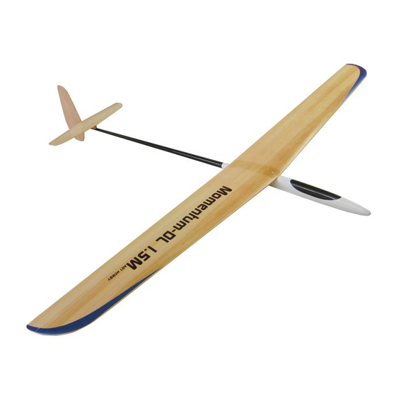
Summary of Contents for Art Hobby Momentum-DL 1.5M
- Page 2 Wing Tips Finishing wing Wood Surfaces 1. Remove the wing segments from their protective foam. To prevent the wood from pre-mature aging and moisture 2. Sand the balsa wing tips to shape. Only round the top. Leave damage, we recommend sealing all wood surfaces using the bottom of the tip the shape of the wing foil.
- Page 3 2. Find the two hardwood blocks. Place the blocks under wing root, center each block under marks you made. 3. Mark the block width on the wing root foam and draw the wing contour line on the block. Photo 4 The blocks will be hard points for the wing mounting screws.
- Page 4 16. Use a small piece of paper towel, fold a few times together and dab the gloss cloth. Photo 10 P. 12 P. 10 Dabbing will allow the epoxy to completely saturate the cloth and adhere to the wood wing surface, it will also remove excess epoxy and smooth the joint.(change new piece of the towel if needed) 17.
-
Page 5: Wing Control Surfaces
9. After epoxy cures remove masking tape. 10. Using sanding block with 320 - 400 grid sand paper sand both servo boxes flush with the wing surface. Photo 16 P. 18 P. 16 Wing Control Surfaces Refer to glider drawing and check ailerons and flaps pencil marked on the wing. - Page 6 4. Place wing bottom side UP. Using metal ruler as a guide and hobby knife with rounded tip blade #11make few straight light strokes cutting bottom veneer sheeting. As soon as the knife tip reaches tape under veneer will start sliding over. Photo 22 5.
- Page 7 Wing Servo Installation and Wiring We recommend HS-45HB Hitec servos to be used for the ailerons 1. Connect each of the aileron servos to the receiver. 2. Turn ON the radio and center servos, use the servo reversing in the transmitter if the servo moves in the wrong direction. 3.
- Page 8 12. Rotate plug face UP then use CA and glue thin planks to the connector walls - boxing it around. Photo 36 P. 39 P. 36 13. Now pulling gently both servo wires and push boxed connector into center opening. If satisfied with fitment mix small amount of 5 min.
- Page 9 P. 42 P. 45 3. Take horns back plate and place on aileron surface centering on the pencil line with front of the plate being flush with front edge of the aileron. Now using pencil make mark on veneer center of each plate hole.
-
Page 10: Wing Mounting
16. To improve aerodynamics and esthetic look of the glider we the board gluing them to the board with CA adhesive. recommend covering aileron servos with Art Hobby’s universal As final step use sewing thread and wrap board with tubes wing servo covers (#A0031). -
Page 11: Tail Installation
3. The bottom part of the carbon mount has a round shape to fit the boom. To insure a perfect fit to the boom wrap the tail part of the boom with 320-400 grid sandpaper then place mount on the paper and pressing it gently down make a few strokes back and forth. - Page 12 8. Now take the board with push-rod tubes and insert longer tube into boom and slide shorter tube over projecting push-rod wire. Photo 64 9. Push board with tubes into boom until stops and elevator tube comes out from its opening and rudder tube from the boom end. Photo 65 P.
- Page 13 16. Mark position and install elevator horn in the center behind elevator mount. When elevator moves down horn should freely retract into narrow slot in back of the mount. Photo 72 & 73 P. 68 P. 72 P. 69 14. If satisfied with fitment glue retainers in place using a few droplets of thin CA adhesive.
- Page 14 19. Using soldering iron (set to low heat) melt projecting post flat with the plate surface and sand melted surface smooth. Photo 76 P. 76 P. 79 20. Hold boom with elevator tube pointing UP then positioning stabilizer mount on the top with front of the mount aligned with masking tape edge then us pencil and outline its position.
- Page 15 26. Mix a small portion of 20min. epoxy and using a small brush apply epoxy to one side of boom and to the vertical stabilizer surface 20mm around the boom. 27. Lay prepared patch of glass cloth centered on the boom and press it to the stabilizer surface covered with epoxy.
- Page 16 7. Secure horn with back plate pushed over the posts. and secure in place with 1-2 droplets of thin CA adhesive. 8. After control horn and back plate is secured the nylon posts should be trimmed to project 1mm above back plate. 9.
- Page 17 25. Before flight, double check balance and control throw direction for free and proper movement. Balancing and Control Throws 1. Before flight, check direction of motor rotation. 2. Double check balance and control throw direction for free and proper movement. 3.


Need help?
Do you have a question about the Momentum-DL 1.5M and is the answer not in the manual?
Questions and answers