Advertisement
Quick Links
Advertisement

Related Manuals for Furniture of America HFW-1860C4


Summary of Contents for Furniture of America HFW-1860C4
- Page 1 HFW-1860C4 Page 1 of 14 REV.18-01-10...
- Page 2 Page 2 of 14...
- Page 3 Page 3 of 14...
- Page 4 Page 4 of 14...
- Page 5 CAM LOCK FASTENER ASSEMBLY INSTRUCTIONS Page 5 of 14...
-
Page 6: Parts List
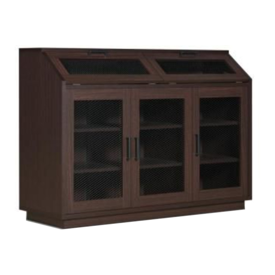
SHOE CABINET ASSEMBLY INSTRUCTIONS MODEL # HFW-1860C4 please keep for future reference PARTS LIST 2PCS 2PCS DIMENSIONS : 47.2"(W)*15.7"(D)*33.4"(H) 2PCS 4PCS 2PCS 2PCS HARDWARE LIST 1 15PCS 2 15PCS 3 16PCS 5 7PCS 6 2SETS 2.2" 7 3SETS 8 2PCS... - Page 7 SHOE CABINET MODEL#HFW-1860C4 Get Ready. Please group boards as below. 2PCS Body 2PCS 4PCS Base 2PCS 2PCS 2PCS Doors/Shelf Page 7 of 14...
- Page 8 ASSEMBLY INSTRUCTIONS STEP : 1 Hardware 1 x 15 pcs Hardware 3 x 16 pcs Hardware 6 x 2 sets Hardware 8 x 2 pcs Hardware 9 x 2 pcs Hardware 10 x 4 pcs front The magnets (#6) are facing outwards.
- Page 9 ASSEMBLY INSTRUCTIONS STEP : 2 Hardware 2 x 2 pcs Hardware 5 x 1 pc Refer to page 5 on how to secure cam locks (#2) to cam bolts (#1). STEP : 3 Hardware 2 x 4 pcs Page 9 of 14...
- Page 10 ASSEMBLY INSTRUCTIONS STEP : 4 Hardware 5 x 6 pcs Hardware 17 x 1 pc Grooves on panel (#B) aligns to back panels (#P). Make sure back panels (#P) are completely flushed within the grooves of the surrounding panels. STEP : 5 Page 10 of 14...
- Page 11 ASSEMBLY INSTRUCTIONS STEP : 6 Hardware 2 x 6 pcs STEP : 7 Hardware 19 x 6 pcs Slightly hammer in the floor protectors (#19) to the bottom of the product. Page 11 of 14...
- Page 12 ASSEMBLY INSTRUCTIONS STEP : 8 Hardware 2 x 3 pcs Hardware 13 x 16 pcs Hardware 14 x 3 sets Attach pins (#13) to the desired height of the shelves (#H,#I). finish STEP : 9 Hardware 7 x 3 sets Attach the push up door pin telescopics (#14) Hardware 14 x 3 sets to the following holes.
- Page 13 ASSEMBLY INSTRUCTIONS STEP : 10 2) Slide the doors (#L,M) to the top holes of panel (#F). 1) Insert the bottom door pins of the doors (#L,M) to the bottom holes of panel (#B). STEP : 11 Align hinges (#12) to the holes of the panels (#J,K), then secure by using screws (#11).
- Page 14 ASSEMBLY INSTRUCTIONS 1) Align hinges (#12) to the STEP : 12 holes of the product as shown in the picture, then secure by Hardware 11 x 12 pcs using screws (#11). 2) Align hinges (#9) to the holes fo the panels (#J,K), then secure by using screws (#11).
Need help?
Do you have a question about the HFW-1860C4 and is the answer not in the manual?
Questions and answers