Table of Contents
Advertisement
Quick Links
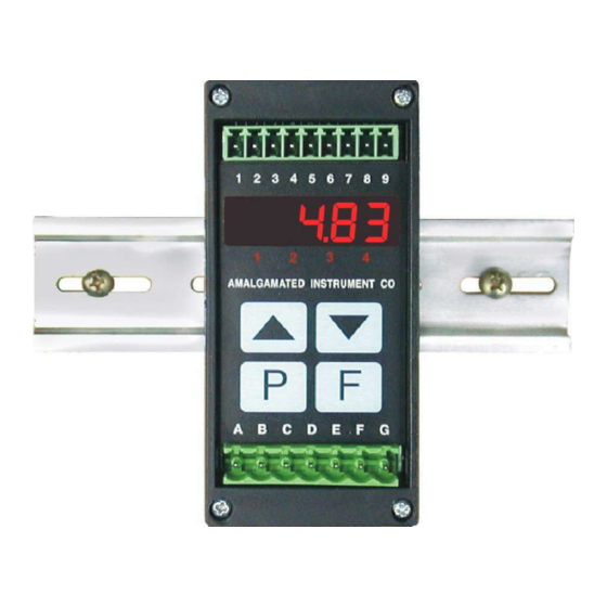
DIN Rail Process Monitor/Controller
Operation and Instruction Manual
AMALGAMATED INSTRUMENT CO
Unit 5, 28 Leighton Place Hornsby
NSW 2077 Australia
Model RM4-AI
Inputs from 0 to 5 Amps
True RMS display
Telephone: +61 2 9476 2244
Facsimile: +61 2 9476 2902
ABN: 80 619 963 692
e-mail: sales@aicpl.com.au
Internet: www.aicpl.com.au
Advertisement
Table of Contents

Related Manuals for AMALGAMATED INSTRUMENT RM4-AI


Summary of Contents for AMALGAMATED INSTRUMENT RM4-AI
- Page 1 Model RM4-AI DIN Rail Process Monitor/Controller Inputs from 0 to 5 Amps True RMS display Operation and Instruction Manual AMALGAMATED INSTRUMENT CO ABN: 80 619 963 692 Unit 5, 28 Leighton Place Hornsby Telephone: +61 2 9476 2244 e-mail: sales@aicpl.com.au...
-
Page 2: Table Of Contents
Table of Contents 1 Introduction 2 Mechanical installation 3 Electrical installation 4 Function tables - summary of setup functions 5 Explanation of functions 6 Calibration 7 Setting up the relay PI controller 8 Specifications 9 Guarantee and service 2 of RM4AIMAN-2.1-0... -
Page 3: Introduction
0 to 5 Amps. For larger AC currents a current transformer can be used to with the instrument then scaled to represent the larger current or in any engineering units. The RM4-AI displays in true RMS. A user selectable “DC” link allows the DC components of a waveform to be taken into account in the true RMS calculation or ignored. - Page 4 Output options 1 or 2 extra relays (not configurable for PI control) Dual output transistor switched 24VDC (non isolated). Isolated 12 bit analog retransmission (single or dual analog output versions available) config- urable for 4–20mA., 0–1V or 0–10V. The first analog output is configurable for retransmission or PI control.
-
Page 5: Mechanical Installation
Mechanical installation The instrument is designed for DIN rail mounting. The instrument clips on to 35mm DIN standard rails (EN50022). Cut the DIN rail to length and install where required. To install the instrument simply clip onto the rail as shown below. To remove the instrument lever the lower arm downwards using a broad bladed screwdriver to pull the clip away from the DIN rail. -
Page 6: Electrical Installation
Electrical installation The RM4 Meter is designed for continuous operation and no power switch is fitted to the unit. It is recommended that an external switch and fuse be provided to allow the unit to be removed for servicing. The terminal blocks allow for wires of up to 2.5mm to be fitted for power supply and relays 1 and 2 or 1.5mm for input connections and optional outputs. - Page 7 Check power supply type before connecting. Relay outputs are voltage free contacts. Remote input connections Choose momentary or latching switch to suit function selected. Remote input The selected remote input function can be operated via an external contact closure via a switch, relay or open collector transistor switch.
- Page 8 Configuring the input board Remove the circuit board from the case following the instructions below. Link settings for the main input board are as shown below. For optional output link settings consult the separate “RM4 DIN Rail Meter Optional Output Addendum” booklet. The DC link allows selection of 0-5A DC input or allows any DC component on an AC waveform to be included in the true RMS measurement.
-
Page 9: Function Tables - Summary Of Setup Functions
Function tables - summary of setup functions Note: the order in which the functions appear on the display may not be exactly as shown below. The availability and order of functions is determined by choice of function settings and options fitted. - Page 10 REC~ 1000 Analog output option high Any display 5.14 display value ( Optional) value REC_ Second analog output option Any display 5.15 low display value ( Optional) value REC~ 1000 Second analog output option Any display 5.16 high display value ( Optional) value drnd 1 to 5000...
- Page 11 A1, A2 LiuE, tARE, LiuE Alarm relay operation mode 5.34 P.HLd, etc. d.HLd, Hi, Lo or dISP LiuE, tARE, LiuE Analog operation mode 5.35 P.HLd, ( Optional) d.HLd, Hi, Lo or dISP REC2 LiuE, tARE, LiuE Second analog operation mode 5.36 P.HLd, ( Optional)
- Page 12 Relay table Record your relay settings in the table below. Note: relay 2 is not available, relays 3 and 4 are optionally fitted. Display Relay 1 Relay 2 Relay 3 Relay 4 AxLo AxHi AxHY Axtt Axrt Axn.o or Axn.c AxSP or Axt1 etc.
-
Page 13: Explanation Of Functions
Explanation of functions The RM4 setup and calibration functions are configured through a push button sequence. The push buttons located at the front of the instrument are used to alter settings. Two basic access modes are available: FUNC mode (simple push button sequence) allows access to commonly set up functions such as alarm setpoints. - Page 14 Example: Entering FUNC mode to change alarm 1 high function A1Hi from OFF to 100 Press & release Press & release Press & release F U N C A 1 H i O F F F until then press until Press &...
- Page 15 Explanation of Functions PI relay control setpoint Ax.SP Display: Range: Any display value Default Value: 0 The control setpoint is set to the value in displayed engineering units required for the control process. The controller will attempt to vary the control output to keep the process variable at the setpoint.
- Page 16 Display Value Relay resets above this Relay value activates A Lo at this value plus or below A HY A HY value A Lo Alarm low operation with hysteresis Time Alarm relay high setpoint AxHi Display: Any display value or OFF Range: Default Value: OFF Displays and sets the high setpoint value for the designated alarm relay x.
- Page 17 Alarm relay hysteresis (deadband) AxHY Display: 0 to 9999 Range: Default Value: 10 Displays and sets the alarm relay hysteresis limit for the designated relay x. Note x will be replaced by the relay number when displayed e.g. A1HY for relay 1. To set a relay hysteresis value go to the AxHY function and use the ^ or v push buttons to set the value required then press F to accept this value.
- Page 18 Alarm relay reset time Axrt Display: 0 to 9999 Range: Default Value: 0 Displays and sets the alarm reset delay time in seconds. The reset time is common for both alarm high and low setpoint values. With the alarm condition is removed the alarm relay will stay in its alarm condition for the time selected as the reset time.
- Page 19 3 had been set at -50 then alarm 3 would activate at 950 (i.e. 1000 – 50). Display brightness brGt Display: 1 to 15 Range: Default Value: 15 Displays and sets the digital display brightness. The display brightness is selectable from 1 to 15, where 1 = lowest intensity and 15 = highest intensity.
- Page 20 Alarm relay one operation mode A1 OPER 5.12 A1 OPEr Display: A1 AL or A1tP or A1Fr Range: Default Value: A1 AL Alarm relay operating mode (relays 1 only) - this function allows selection of standard alarm on/off setpoint operation (A1.AL) using the alarm functions described in this chapter or PI control operation (A1.tP or A1.fr).
- Page 21 5.15 Second analog output option low value REC_ Display: Range: Any display value Default Value: 0 See REC_ function 5.13 for description of operation. 5.16 Second analog output option high value REC~ Display: Range: Any display value Default Value: 1000 See REC~ function 5.14 for description of operation.
- Page 22 5.19 Digital filter FLtr Display: 0 to 8 Range: Default Value: 2 Displays and sets the digital filter value. Digital filtering uses a weighted average method of determining the display value and is used for reducing display value variation due to short term interference.
- Page 23 5.23 Calibration offset CAL OFSt Display: Range: Any display value Default Value: n/a Calibration offset - See section 6.2. 5.24 Zero range ZERO RNGE Display: Any display value or OFF Range: Default Value: OFF Zero range limit value - see section 6.3. Zero reference point for ZERO RNGE operation 5.25 CAL ZERO...
- Page 24 5.28 Uncalibrate UCAL Display: Range: Default Value: n/a Uncalibrate, resets calibration - required only when a calibration problem occurs and it is necessary to clear the calibration memory. At the UCAL function press the ^ and v buttons simultaneously. The message CAL CLr should be seen to indicate that the calibration memory has been cleared. P button function 5.29 Pbut...
- Page 25 5.30 Remote input one function R.INP Display: NONE, P.HLd, d.HLd, Hi, Lo , HiLo, tARE, ZERO, SP.Ac, No.Ac, Range: CAL.S or duLL Default Value: NONE Remote input function - When these remote input terminals are short circuited, via a switch, relay, keyswitch etc.
- Page 26 input terminals open circuit and another set with the remote input terminals short circuit to ground. The remote input can then be used to switch between one set and the other. This allows two different load cells to be connected with a remote input being used to select the correct scaling for each or the same load cell could be used and the remote input used to toggle between different display units.
- Page 27 5.33 Square root mode SQrt Display: on or OFF Range: Default Value: OFF Not applicable to this software version, this function must be left set to OFF. 5.34 Alarm relay operation mode A1, A2 etc. Display: LiuE, tARE, P.HLd, d.HLd, Hi, Lo or dISP Range: Default Value: LiuE Alarm relay operation mode for relays 1, 2 etc.
- Page 28 5.35 Analog output operation mode Display: LiuE, tARE, P.HLd, d.HLd, Hi, Lo or dISP Range: Default Value: LiuE This section describes the operation modes available for the retransmission options REC (analog retransmission) operation mode. The following choices are available: LiuE - live input mode. The retransmission will follow the electrical input and will not necessarily follow the 7 segment display.
- Page 29 5.36 Second analog output mode REC2 Display: LiuE, tARE, P.HLd, d.HLd, Hi, Lo or dISP Range: Default Value: LiuE Analog output mode for second analog output. Operates in the same manner as the first analog output, see function 5.35. 5.37 Low overrange visual warning limit value Lo dISP Display:...
- Page 30 function is set to -or- then the -or- message will flash on and off once a second as a visual warning. The warning flashes will cease and the normal display value will be seen when the value displayed is higher than the low limit and lower than the high limit. 5.40 Baud rate for optional serial communications bAUd RAtE...
- Page 31 5.43 Instrument address for optional serial communications Addr Display: 0 to 31 Range: Default Value: 0 Set unit address for polled (POLL) or M.buS mode (0 to 31)) - seen only with serial output option. Refer to the separate “RM4 Din Rail Meter Optional Output Addendum” booklet supplied when optional outputs are fitted.
-
Page 32: Calibration
Calibration Note: when using a current transformer the resistance of the wire between the current transformer and the RM4 can change the output from the current transformer. To avoid inaccurate calibration once the RM4 has been calibrated the length or type of wire should not be changed. Live signal input calibration CAL1 and CAL2 are used together to scale the instruments display, values for both must be set when using this scaling method. - Page 33 Offset calibration CAL OFSt - Calibration offset - the calibration offset is a single point adjustment which can be used to alter the calibration scaling values across the entire measuring range without affecting the calibration slope. This method can be used instead of performing a two point calibration when a constant measurement error is found to exist across the entire range.
- Page 34 Uncalibration UCAL - Uncalibrate - used to set the instrument back to the factory calibration values. This function should only be used when calibration problems exist and it is necessary to clear the calibration memory. To clear the calibration memory press the ^ and v buttons simultaneously at the UCAL function.
-
Page 35: Setting Up The Relay Pi Controller
Setting up the relay PI controller The Relay Proportional + Integral Controller can be made to operate in either pulse width control or frequency control mode via the Ax OPEr function. Note that the Ax OPEr function will not be seen until a value has been set for the low or high alarm e.g. for A1Lo or A1Hi. The best results are usually achieved by initially configuring as a “Proportional Only”... - Page 36 PI relay control setpoint Ax.SP Display: Range: Any display value Default Value: 0 The control setpoint is set to the value in displayed engineering units required for the control process. The controller will attempt to vary the control output to keep the process variable at the setpoint.
- Page 37 PI relay proportional gain Ax.PG Display: -32.767 to 32.767 Range: Default Value: 0.010 Note: the range value may be restricted if the number of display digits does not allow viewing of the full range. The proportional value will determine the degree to which the controller will respond when there is a difference (error) between the measured value and the process setpoint.
- Page 38 This table shows the effect of the output frequency of changing proportional gain and bias with the following settings: ctrI SPAN = 20, A1.dc = 1.0, A1.IG = 0.000 A1.SP A1.PG A1.bS Effect on relay operation 1.000 Reading of 50 or below - relay permanently on. Reading of 50 to 70 - relay pulses with off...
- Page 39 unable to correct (e.g. errors caused by changes in the process load). When the integral gain is correctly adjusted the control output is varied to maintain control by keeping the process variable at the same value as the control setpoint. Since the integral gain is time based the output will gradually increase if the error does not decrease i.e.
- Page 40 PI relay integral control low limit Ax.IL Display: 0.0 to 100.0 Range: Default Value: 100.0 The minimum limit can be used to reduce overshoot of the control setpoint when the control output is being reduced i.e. falling below the setpoint. The low limit reduces the available output swing by a percentage of the maximum output.
- Page 41 control relay and the controlling device. Relay etc. period period period 7.10 Setting up the PI pulse width controller 1. Set the Ax OPEr function to Ax.tP. 2. Set the control setpoint Ax.SP to the required setting. 3. Set the control span ctrI SPAN to the required setting. 4.
- Page 42 7.11 Relay frequency modulation control mode To use pulse width modulation control Ax.Fr must be selected at the Ax OPEr function. In frequency modulation mode the relay on time is fixed. A minimum relay off time can also be set. The control program will vary the actual off...
- Page 43 This table shows the effect of the output frequency of changing proportional gain and bias with the following settings: ctrI SPAN = 20, A1.dc = 1.0, A1.IG = 0.000 A1.SP A1.PG A1.bS Effect on relay operation 1.000 Reading of 50 or below - relay pulses at maximum frequency. Reading of 50 to 70 - relay pulses with frequency decreasing as value approaches 70.
- Page 44 3. Set the control span ctrI SPAN to the required setting. 4. Set the proportional gain Ax.PG to an arbitrary value e.g. 0.500. 5. Set the integral gain Ax.IG to 0.000 (i.e. off). 6. Set the low and high integral Ax.IL and Ax.IH limits to an arbitrary value e.g. 20.00. 7.
-
Page 45: Specifications
Specifications Technical specifications Input: 0-5A AC or 0-5A DC link selectable Impedance: Less than 50mΩ Accuracy: 0.5% of full scale 1 display digit for alarms and display when calibrated. Sample rate: 7.5 samples per second ADC Resolution: 1 in 20,000 Display update: 4 per second Conversion Method:... -
Page 46: Guarantee And Service
Guarantee and service The product supplied with this manual is guaranteed against faulty workmanship for a period of two years from the date of dispatch. Our obligation assumed under this guarantee is limited to the replacement of parts which, by our examination, are proved to be defective and have not been misused, carelessly handled, de- faced or damaged due to incorrect installation.
Need help?
Do you have a question about the RM4-AI and is the answer not in the manual?
Questions and answers