Table of Contents
Advertisement
Quick Links
Reference Manual
(Software)
CODESYS Modbus Master CPU Unit
CPSN-PCB271-S1-041
CONTENTS
Introduction .................................................................. 5
Safety Precautions .................................................... 11
Set the Computer Network ................................... 15
CONPROSYS nano WEB Setting.......................... 21
CODESYS Installation .............................................. 49
Basic Programming .................................................. 55
Programing with CODESYS ................................... 76
Maintenance ............................................................ 133
Troubleshooting ..................................................... 137
Appendix ................................................................... 140
Customer Support and Inquiry ......................... 152
Advertisement
Table of Contents

Related Manuals for Contec CONPROSYS nano CPSN-PCB271-S1-041


Summary of Contents for Contec CONPROSYS nano CPSN-PCB271-S1-041
- Page 1 Reference Manual (Software) CODESYS Modbus Master CPU Unit CPSN-PCB271-S1-041 CONTENTS Introduction ..............5 Safety Precautions ............ 11 Set the Computer Network ........15 CONPROSYS nano WEB Setting......21 CODESYS Installation ..........49 Basic Programming ..........55 Programing with CODESYS ........76 Maintenance ............
-
Page 2: Table Of Contents
Table of Contents Introduction ............... 5 1. Procedure until ready to use ..........................6 2. Related manuals ..............................7 3. Check the firmware version ..........................8 4. About the product ..............................9 5. Features ................................... 10 Safety Precautions ............11 1. - Page 3 Table of Contents 15. Shutdown ................................. 47 16. Logout ................................48 CODESYS Installation ............49 1. Installation of the CODESYS ..........................50 2. Installation of the Package ..........................52 3. PC and CONPROSYS nano cable connection ................... 53 Basic Programming ............55 1.
- Page 4 Table of Contents 2. Create a Project ............................. 95 3. Add Modbus Devices (When using Modbus TCP) ................96 4. Add Modbus Devices (When using Modbus RTU) ................98 5. I/O Variable Definition ..........................100 6. Create and build a program ........................102 7.
-
Page 5: Introduction
Introduction This section provides necessary information of the product such as the product configuration and manuals before actual use. — 5 —... -
Page 6: Procedure Until Ready To Use
— — Introduction CPSN-PCB271-S1-041 Reference Manual (Software) 1. Procedure until ready to use The following chart shows the standard procedure until the product is ready to use. Connect with a PC Refer to Page 16 Set up the network of PC Refer to Page 17 Set up with CONPROSYS nano WEB Setting Refer to Page 21... -
Page 7: Related Manuals
Reference Manual for I/O Read this when operating This describes the Download from Module (Hardware) the I/O module with CPU hardware aspects such as the CONTEC Unit. functions and settings of website (PDF) the I/O module. Reference Manual for Read this when operating... -
Page 8: Check The Firmware Version
Before running the product, visit our website to check the firmware version and update to the latest one if necessary. Updating firmware to the latest version will resolve troubles and stabilize the operation. https://www.contec.com/download/ Download Refer to the “Firmware Update (page 39)” for further details. -
Page 9: About The Product
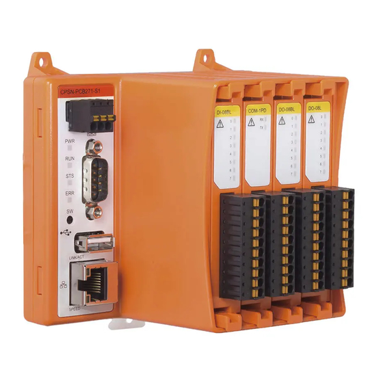
— — Introduction CPSN-PCB271-S1-041 Reference Manual (Software) 4. About the product This product is a CPU unit with RS-232C, LAN interface and four expansion slots, and supports CODESYS programming and Modbus Master. Configurable I/O modules of the CONPROSYS nano series can be arranged and combined along with the product to satisfy the user’s needs. —... -
Page 10: Features
— — Introduction CPSN-PCB271-S1-041 Reference Manual (Software) 5. Features The product features the CODESYS SoftPLC CODESYS is a device-independent-PLC-programming system that is compliant with the IEC 61131-3 standard and supports all standard programming languages such as ST or LD. ... -
Page 11: Safety Precautions
Safety Precautions Understand the following definitions and precautions to use the product safely. Never fail to read them before using the product. — 11 —... -
Page 12: Safety Information
— — Safety Precautions CPSN-PCB271-S1-041 Reference Manual (Software) 1. Safety Information This document provides safety information using the following symbols to prevent accidents resulting in injury or death and the destruction of equipment and resources. Understand the meanings of these labels to operate the equipment safely. DANGER DANGER indicates an imminently hazardous situation which, if not avoided, will result in death or serious injury. -
Page 13: Handling Precautions
CONTEC’s website and understand the contents. Do not modify the software. CONTEC will bear no responsibility for any problems, etc., resulting from modifying the software. Regardless of the foregoing statement, CONTEC assumes no responsibility for any errors that ... -
Page 14: Security Warning
— — Safety Precautions CPSN-PCB271-S1-041 Reference Manual (Software) 3. Security Warning When connecting to the network, be aware of security-related problems. See the examples of Security measures below and set up the product properly along with the network devices. 1. Information security risks Unauthorized access from the outside through a network could cause the system halt, data ... -
Page 15: Set The Computer Network
Set the Computer Network This section describes how to connect the product with a PC, set the network, and check the communication. — 15 —... -
Page 16: Connect With A Pc
— — Set the Computer Network CPSN-PCB271-S1-041 Reference Manual (Software) 1. Connect with a PC To set the product, you need to first set up the network between the PC and the product in order to establish communication. First, connect the product with the PC. Follow the instructions below to connect the computer, the controller, and the power unit. -
Page 17: Set The Computer Network
— — Set the Computer Network CPSN-PCB271-S1-041 Reference Manual (Software) 2. Set the Computer Network Follow the “Computer Network Setting Procedure” described below and set the network to make the IP addresses as shown. The product must set a unique IP address for the bold part (200 or 101) that is not used by other devices on your network. - Page 18 — — Set the Computer Network CPSN-PCB271-S1-041 Reference Manual (Software) Double-click the appeared [Ethernet] Click the [Property] in [Ethernet Status] dialog box. Double-click the [Internet protocol version 4(TCP/IPv4)] in [Ethernet Properties] dialog box. — 18 —...
- Page 19 — — Set the Computer Network CPSN-PCB271-S1-041 Reference Manual (Software) In the [Internet protocol version 4 (TCP/IPv4) property], set IP address and Subnet mask as shown below. Click the [OK] → the [OK] → the [Close] to close the dialog box and complete the network setting.
-
Page 20: Check Communication
— — Set the Computer Network CPSN-PCB271-S1-041 Reference Manual (Software) 3. Check Communication Start the Internet Explorer 11 on your computer. Enter IP address (10.1.1.101) of the controller in the address bar, then press [Enter] key. The dialog box asking for the Password appears, enter it and click the [Login]. Refer to “Setup Using a Web Browser (page 22) for details of compatible web browser. -
Page 21: Conprosys Nano Web Setting
CONPROSYS nano WEB Setting This section describes the product system and functions. — 21 —... -
Page 22: Conprosys Nano Web Setting Outline
— — CONPROSYS nano WEB Setting CPSN-PCB271-S1-041 Reference Manual (Software) 1. CONPROSYS nano WEB Setting Outline Configure the system and individual setting on [CONPROSYS nano WEB Setting]. CONPROSYS nano WEB Setting can be displayed or configured easily through web browser. 1. -
Page 23: Start Up Conprosys Nano Web Setting
— — CONPROSYS nano WEB Setting CPSN-PCB271-S1-041 Reference Manual (Software) 3. Start up CONPROSYS nano WEB Setting Start up a web browser of the PC connected with this product. Enter the IP address (10.1.1.101) of the controller in the address bar and press the [Enter] key. The dialog box asking for the Password appears, enter it and click the [Login]. -
Page 24: Conprosys Nano Web Setting Basic Operation
— — CONPROSYS nano WEB Setting CPSN-PCB271-S1-041 Reference Manual (Software) 4. CONPROSYS nano WEB Setting Basic Operation CONPROSYS nano WEB Setting Page Structure Click the menu item on the left side of the screen. This opens a page to set the details of the menu on the right side of the screen. -
Page 25: Menu Function List
— — CONPROSYS nano WEB Setting CPSN-PCB271-S1-041 Reference Manual (Software) 2. Menu Function List Menu Functions are listed below. Menu item name Function Description Setting Configure the system of the product including IP address, subnet Page 26 System mask, default gateway, language, and password. Set the I/O module installed in the expansion slot. -
Page 26: Function Details
— — CONPROSYS nano WEB Setting CPSN-PCB271-S1-041 Reference Manual (Software) 3. Function Details 1. System Configure the system of the product including IP address, subnet mask, default gateway, language, and password. IP Address Set the IP address for this product. [Setting]: IP address [Default]: 10.1.1.101 ... - Page 27 — — CONPROSYS nano WEB Setting CPSN-PCB271-S1-041 Reference Manual (Software) Language Set the language to be displayed on the web setting page. [Setting]: Japanese, English [Default]: Japanese Time Zone Set the time zone according to the country where this product is used. [Setting]: -12:00 - +13:00 [Default]: +09:00 ...
-
Page 28: I/O Module
— — CONPROSYS nano WEB Setting CPSN-PCB271-S1-041 Reference Manual (Software) 2. I/O Module Set the I/O module installed in the expansion slot. The displayed contents vary depending on the I/O module installed in the expansion slot. Transfer Mode Set communication method for data transmission. CPSN-COM-1PD [Setting]: Full Duplex, Half Duplex [Default]: Full Duplex... - Page 29 — — CONPROSYS nano WEB Setting CPSN-PCB271-S1-041 Reference Manual (Software) Input Method Set the connection method of input analog signal. With the CPSN-AI-2408LI, only Differential Input is available when one of the switches is set to "Current Input". CPSN-AI-2408LI [Setting]: Single-ended Input, Differential Input [Default]: Single-ended Input ...
- Page 30 — — CONPROSYS nano WEB Setting CPSN-PCB271-S1-041 Reference Manual (Software) Channel Switching Rate The channel switches in sequence at the set switching rate, and the value of the analog input data register is updated. The longer the time is set, the lower the frequency noise can be removed. The present value of the analog input data register remains until the next switching starts.
- Page 31 — — CONPROSYS nano WEB Setting CPSN-PCB271-S1-041 Reference Manual (Software) Operation Mode Set the counter operation mode. 2-phase input is two pulse inputs, A-phase (a lead signal) and B-phase (a lag signal) that differ in phase by 90 °. When there is a Z-phase (position reference signal), the count value can be cleared to zero with a 2- phase pulse input.
- Page 32 — — CONPROSYS nano WEB Setting CPSN-PCB271-S1-041 Reference Manual (Software) Phase-Z Input Logic Set the phase-Z input logic. When this is set as Positive-logic, the count values are cleared to zero at phase-Z active high. CPSN-CNT-3201I [Setting]: Positive-logic (active high), Negative-logic (active low) [Default]: Positive-logic (active high) ...
-
Page 33: Network Time
— — CONPROSYS nano WEB Setting CPSN-PCB271-S1-041 Reference Manual (Software) 3. Network Time Set up the name of NTP server that obtains the time and date. Network Time Function By enabling the network time function and setting the IP address and time zone of the NTP server, the time of this product can be synchronized with the network time. -
Page 34: Log
— — CONPROSYS nano WEB Setting CPSN-PCB271-S1-041 Reference Manual (Software) 4. Log Set the log functions. Log Function To record the log for this product using the log function, set to "Enabled". You can prevent the log from being recorded by setting this setting to "Disabled", but in normal operation this is unnecessary. -
Page 35: System
— — CONPROSYS nano WEB Setting CPSN-PCB271-S1-041 Reference Manual (Software) 5. System Display the system information such as firmware version, serial number, and MAC address. Loader Version Shows the loader version. Firmware Version Shows the firmware version. Serial Number Shows the serial number. - Page 36 — — CONPROSYS nano WEB Setting CPSN-PCB271-S1-041 Reference Manual (Software) Uptime Shows the uptime from startup of the device. Operating State Shows the operating state of the device. Operating State Description Initializing The device initialization is in progress. Operating The state of the device indicates that it is accessible.
-
Page 37: Log Information
— — CONPROSYS nano WEB Setting CPSN-PCB271-S1-041 Reference Manual (Software) 6. Log Information Shows the log recorded by this product. If the number of log entries exceeds 300 entries, the most recent 300 entries are displayed. If you want to check all the logs, you can download the current log information by clicking [logfile] at the bottom of the Log page. - Page 38 — — CONPROSYS nano WEB Setting CPSN-PCB271-S1-041 Reference Manual (Software) Log content Category Description Category Event Network Time Time Set Time was set User USER Manual Reset Restart by administrator — 38 —...
-
Page 39: Firmware Update
— — CONPROSYS nano WEB Setting CPSN-PCB271-S1-041 Reference Manual (Software) 7. Firmware Update Update the firmware of the product. Click the [Browse] button and select the firmware to update. Then click the [Update] to start uploading. It takes about 15 seconds to complete the uploading and updating. The screen display is changed upon completion. -
Page 40: Configuration File
— — CONPROSYS nano WEB Setting CPSN-PCB271-S1-041 Reference Manual (Software) 8. Configuration File Backup and restore the configuration file of the product. Backup Click link to download the configuration file of the product that is used currently. The name of the downloading file is with .txt extension. -
Page 41: Time Adjustment
— — CONPROSYS nano WEB Setting CPSN-PCB271-S1-041 Reference Manual (Software) 9. Time Adjustment Set the date and the time for this product. Enter the year as four digits, the month, the day, the hour (24hour time), the minute, and the seconds, and then click the update button. When the month and day are a single digit, a 0 is added and they are displayed as two digits. -
Page 42: Default Setting
— — CONPROSYS nano WEB Setting CPSN-PCB271-S1-041 Reference Manual (Software) 10. Default Setting You can restore the settings of this product to the default settings. At this time, select with the radio button to also restore the IP addresses (including subnet mask) to the defaults or to leave them as they are. -
Page 43: Plc Program
— — CONPROSYS nano WEB Setting CPSN-PCB271-S1-041 Reference Manual (Software) 11. PLC Program Save, delete, and upload the PLC program. Save the PLC program Save the PLC program that is operating on RAM into ROM area. Select the [Save the PLC program into ROM area.] and click the [Execute] button. PWR, RUN, and STS of LEDs on the front of the product keep flashing simultaneously until writing has been completed. -
Page 44: Save & Reboot
— — CONPROSYS nano WEB Setting CPSN-PCB271-S1-041 Reference Manual (Software) 12. Save & Reboot Save the configured settings before rebooting the product. In a pop-up dialog box, click [OK] to save the settings and reboot the product. — 44 —... -
Page 45: Save
— — CONPROSYS nano WEB Setting CPSN-PCB271-S1-041 Reference Manual (Software) 13. Save Save the configured settings. In a pop-up dialog box, click [OK] to save the settings. The saved settings will be available after rebooting the product. — 45 —... -
Page 46: Reboot
— — CONPROSYS nano WEB Setting CPSN-PCB271-S1-041 Reference Manual (Software) 14. Reboot Reboot the product. In a pop-up dialog box, click [OK] to reboot the product. — 46 —... -
Page 47: Shutdown
— — CONPROSYS nano WEB Setting CPSN-PCB271-S1-041 Reference Manual (Software) 15. Shutdown Shut down the product. In a pop-up dialog box, click [OK] to shut down the product. When the shutdown is completed, the PWR of LED will be off, also RUN and STS of LED will start flashing. -
Page 48: Logout
— — CONPROSYS nano WEB Setting CPSN-PCB271-S1-041 Reference Manual (Software) 16. Logout Log out of the product. In a pop-up dialog box, click [OK] to log out. Perform this to exit when you do not reboot or shut down the product. —... -
Page 49: Codesys Installation
CODESYS Installation This section describes the CODESYS installation procedure. — 49 —... -
Page 50: Installation Of The Codesys
— — CODESYS Installation CPSN-PCB271-S1-041 Reference Manual (Software) 1. Installation of the CODESYS This product can run with the CODESYS software, which is a device-independent-PLC-programming system that is compliant with the IEC 61131-3 standard. To use the CODESYS, installation of the CODESYS development environment and “CODESYS Package” for CONPROSYS nano are required. - Page 51 — — CODESYS Installation CPSN-PCB271-S1-041 Reference Manual (Software) In the “Registered Customers”, enter “Email Address” and “Password” to log in. After log-in, click the “Download” to start downloading. Decompress the downloaded file, and execute the setup file (extention.exe file) to install CODESYS.
-
Page 52: Installation Of The Package
To use this product with the CODESYS, installation of CODESYS Package for CONPROSYS nano is necessary. Go to the CONTEC website. From the menu Downloads, select [Drivers & Software]. Enter the product name or specify the category (Remote I/O (nano series)) and click the [Search]. -
Page 53: Pc And Conprosys Nano Cable Connection
— — CODESYS Installation CPSN-PCB271-S1-041 Reference Manual (Software) 3. PC and CONPROSYS nano cable connection Connect the LAN port of CODESYS development PC and the LAN port of this controller with Ethernet cable. Power on the controller. Change network setting for PC. LAN port of this product is set to “10.1.1.101”... - Page 54 — — CODESYS Installation CPSN-PCB271-S1-041 Reference Manual (Software) * The PLC controller must set a unique IP address that is not used by other devices on your network. IP address of PLC controller can be set through web browser. * Refer to “Set the Computer Network (page 15)“ for detailed settings of ID address. Use the ping command and confirm that PLC controller is connected with the PC.
-
Page 55: Basic Programming
Basic Programming This section describes basic procedure to operate this product with CODESYS. — 55 —... -
Page 56: Nomenclature Of Codesys Components
Components The basic screen display of CODESYS is viewed as below. 1. Device window, Device Configuration window Double-click the “Device (CODESYS Control CONTEC CPSN-PCB271-S1)” icon on Device window to open Device Configuration window. 2. ST Editor window Double-click the “PLC_PRG (PRG)” icon on Device window to open ST Editor window. -
Page 57: Format And Programming Of St Language
— — Basic Programming CPSN-PCB271-S1-041 Reference Manual (Software) 2. Format and programming of ST language ST language is used for an example programming in this manual. Formats of basic ST language such as assignment expression, conditional expression, and commenting out are listed. ... - Page 58 — — Basic Programming CPSN-PCB271-S1-041 Reference Manual (Software) Conditional expression (IF - THEN) Determine a condition, then execute or skip routine. IF StartFlag THEN (Routine) END_IF If a value of variable [StartFlag] is [True], then execute the routine placed between END_IF. ...
-
Page 59: Basic Programming Procedure
Specify the (3) Name and the (4) Location of the project, then click the [OK]. In the Standard Project dialog, select the controller to be used in the (6) [Device]. Device can be shown as [CODESYS Control CONTEC CPSN-PCB271-S1]. From the (7) “PLC_PRG”, choose Structured Text (ST). -
Page 60: Connect Controller From Codesys
Basic Programming CPSN-PCB271-S1-041 Reference Manual (Software) 2. Connect controller from CODESYS On the Devices window, double click the (1) “Device (CODESYS Control CONTEC CPSN- PCB271-S1)” icon to open “Device Configuration window”. Select the (2) [Communication Settings] in the Device tab. -
Page 61: Add I/O Modules
— — Basic Programming CPSN-PCB271-S1-041 Reference Manual (Software) 3. Add I/O modules This product can add I/O modules in a free combination. Right-click on the controller of CODESYS device window and select the [Add device]. In the dialog box, select the I/O module you wish to add and click the [Add device] button. I/O modules are located under the tree hierarchy of the [Miscellaneous]. -
Page 62: I/O Variable Definition
— — Basic Programming CPSN-PCB271-S1-041 Reference Manual (Software) 4. I/O Variable Definition In order to input or output with CODESYS, input variable to I/O Mapping or Parameters, and define variables of I/O channel. In this example, assigning variable [DO00] in bit 0 of CPSN-DO-08BL DO port is defined as I/O variables. -
Page 63: Create A Program And Build
— — Basic Programming CPSN-PCB271-S1-041 Reference Manual (Software) 5. Create a program and build Create PLC program with defined I/O variable“DO0” that is demonstrated in the previous page “I/O Variable Definition (page 62)“, and set ON output from digital output [Bit0]. This example demonstrates programming with ST language. -
Page 64: Download And Run Program
— — Basic Programming CPSN-PCB271-S1-041 Reference Manual (Software) 6. Download and run program When building a program demonstrated in the previous page “Create a program and build (page 63)“ is completed, log in from [Online] – [Login] on CODESYS menu. Click the [Yes] in the download confirmation dialog. -
Page 65: Save The Plc Program Into Rom
— — Basic Programming CPSN-PCB271-S1-041 Reference Manual (Software) 7. Save the PLC program into ROM Since the PLC program is downloaded to RAM, the program will be disposed upon shutting down. If you want to avoid this, save the programs into ROM area. ... - Page 66 — — Basic Programming CPSN-PCB271-S1-041 Reference Manual (Software) How to save 2 To write the same PLC program in two or more devices, follow the instruction below. In CODESYS development environment, open the project of the program you plan to save. Select [Online] - [Create boot application] on CODESYS menu.
-
Page 67: Delete The Plc Program Saved In Rom
— — Basic Programming CPSN-PCB271-S1-041 Reference Manual (Software) 8. Delete the PLC program saved in ROM To delete the PLC program stored on ROM area, perform the steps described below. How to delete 1 Log in to the controller under the CODESYS development environment. * See “Connect controller from CODESYS (page 60)“... -
Page 68: If An Error Occurs Under The Codesys Development Environment
— — Basic Programming CPSN-PCB271-S1-041 Reference Manual (Software) 9. If an error occurs under the CODESYS development environment An error occurs if required CODESYS libraries to execute the created program are missing. To begin with, follow the steps instructed below to check whether the libraries are sufficient. If not, download missing libraries. -
Page 69: Interface Definition Per Model
— — Basic Programming CPSN-PCB271-S1-041 Reference Manual (Software) 4. Interface definition per model How to define I/O interface of Parameter, I/O Mapping, and Serial port with CODESYS are described below. 1. Parameter Parameter is set only once upon starting a controller. It is listed in the [Internal Parameters] on CODESYS. - Page 70 — — Basic Programming CPSN-PCB271-S1-041 Reference Manual (Software) CPSN-AI-1208LI I/O Mapping Name Notation on CODESYS Size Number Access Remarks Higher 4 bits: 0 fixed Analog input data ai 0-7 16bit Lower 12 bits: Measurement data *1 Analog input data ai 0-7 32bit (Industrial value) (industrial value)
- Page 71 — — Basic Programming CPSN-PCB271-S1-041 Reference Manual (Software) CPSN-DI-16BCL I/O Mapping Name Notation on CODESYS Size Number Access Remarks Digital input data digital input bit 0-15 16bit 0=OFF, 1=ON counter input Counter input data 32bit channel 0-15 match status input 0=Not detected Count match status 16bit...
- Page 72 — — Basic Programming CPSN-PCB271-S1-041 Reference Manual (Software) *2 The measurement data are returned in an integer value 0 - 16777215. When converting the measurement data into voltage or current values, use the following conversion formula. Conversion formula: Input voltage (V) = Measurement data x Span / 2 - Off-set Input current (mA) = Measurement data x Span / 2 - Off-set...
- Page 73 — — Basic Programming CPSN-PCB271-S1-041 Reference Manual (Software) CPSN-SSI-4C I/O Mapping Name Notation on CODESYS Size Number Access Remarks SSI input data 32bit ssi input channel 0-3 SSI input data 32bit ssi input (Industrial value) (industrial value) channel 0-3 *1 SSI input data details Conversion formula: Temperature (°C) = Temperature data / 1024 Conversion examples:...
- Page 74 — — Basic Programming CPSN-PCB271-S1-041 Reference Manual (Software) CPSN-DIO-08SL I/O Mapping Name Notation on CODESYS Size Number Access Remarks Digital input data di 0-7 8bit 0=OFF, 1=ON Digital output data do 0-7 8bit 0=OFF, 1=ON CPSN-RRY-4PCA I/O Mapping Name Notation on CODESYS Size Number Access...
-
Page 75: Serial Port
— — Basic Programming CPSN-PCB271-S1-041 Reference Manual (Software) *2 Set the voltage value (V) or current value (mA) in single-precision floating- point number type. For example, set "1.5" if outputting 1.5V. *3 I/O variable in analog output data and analog output data (industrial value) cannot be used at the same time. -
Page 76: Programing With Codesys
Programing with CODESYS This section describes the CODESYS programming procedure per function. — 76 —... -
Page 77: Serial Communication
— — Programing with CODESYS CPSN-PCB271-S1-041 Reference Manual (Software) 1. Serial Communication 1. Device setting Connect a controller and a PC via serial cable to send data from the controller to the PC and receive data from the PC to the controller. Use COM port within the controller. 2. -
Page 78: Create A Transmission Program
— — Programing with CODESYS CPSN-PCB271-S1-041 Reference Manual (Software) 4. Create a transmission program Create a Program Double click the [PLC_PRG (PRG)] icon on the device window to open the “ST editor window”. When “ST editor window” appears, write the following source code between VAR and END_VAR in the “Variable declaration”. - Page 79 — — Programing with CODESYS CPSN-PCB271-S1-041 Reference Manual (Software) IF StartFlag THEN CASE State OF Com1Params[1].udiParameterId := COM.CAA_Parameter_Constants.udiPort; Com1Params[1].udiValue := 1; Com1Params[2].udiParameterId := COM.CAA_Parameter_Constants.udiBaudrate; Com1Params[2].udiValue := 9600; Com1Params[3].udiParameterId := COM.CAA_Parameter_Constants.udiParity; Com1Params[3].udiValue := INT_TO_UDINT(COM.PARITY.NONE); Com1Params[4].udiParameterId := COM.CAA_Parameter_Constants.udiStopBits; Com1Params[4].udiValue := INT_TO_UDINT(COM.STOPBIT.ONESTOPBIT); Com1Params[5].udiParameterId := COM.CAA_Parameter_Constants.udiTimeout; Com1Params[5].udiValue := 0;...
-
Page 80: Create A Reception Program
— — Programing with CODESYS CPSN-PCB271-S1-041 Reference Manual (Software) Now, see whether you can execute [Rebuild”] in CODESYS [Build] menu to confirm the process succeeds. Character string transmission Select [Online] - [Login] on CODESYS menu. Click [Yes] in the download confirmation dialog. With terminal connected to serial port from PC, wait in a reception state. - Page 81 — — Programing with CODESYS CPSN-PCB271-S1-041 Reference Manual (Software) Write the following source code in “Program” under “ST editor window”. IF StartFlag THEN CASE State OF Com1Params[1].udiParameterId := COM.CAA_Parameter_Constants.udiPort; Com1Params[1].udiValue := 1; Com1Params[2].udiParameterId := COM.CAA_Parameter_Constants.udiBaudrate; Com1Params[2].udiValue := 9600; Com1Params[3].udiParameterId := COM.CAA_Parameter_Constants.udiParity; Com1Params[3].udiValue := INT_TO_UDINT(COM.PARITY.NONE);...
- Page 82 — — Programing with CODESYS CPSN-PCB271-S1-041 Reference Manual (Software) Error := TRUE; END_IF IF Com1Close.xDone OR Com1Close.xError THEN State := 1000; END_IF 1000: StartFlag := FALSE; END_CASE END_IF Now, see whether you can execute [Rebuild”] in CODESYS [Build] menu to confirm the process succeeds.
- Page 83 — — Programing with CODESYS CPSN-PCB271-S1-041 Reference Manual (Software) Character string transmission Select [Online] - [Login] on CODESYS menu. Click [Yes] in the download confirmation dialog. With terminal connected to serial port from PC, wait in a transmission state. Enter a break point in a reception-function of program source cord.
-
Page 84: Modbus Master
— — Programing with CODESYS CPSN-PCB271-S1-041 Reference Manual (Software) 2. Modbus Master 1. Device setting Use a controller as Modbus Master to input/output data with Modbus Slave. Following is an example case when the CPSN-MCB271-S1-041 containing the CPSN-DO-08BL and CPSN-DI-08BL in the slots is used as Modbus Slave. Connect the CODESYS Developing PC with the controller and Modbus Slave. -
Page 85: Add Modbus Devices (When Using Modbus Tcp)
— — Programing with CODESYS CPSN-PCB271-S1-041 Reference Manual (Software) 3. Add Modbus Devices (When using Modbus TCP) Add Ethernet Adapter Right-click on the controller of the device window and select [Add Device]. In the dialog box, select [Fieldbuses - Ethernet Adapter - Ethernet] and click [Add Device] button. - Page 86 — — Programing with CODESYS CPSN-PCB271-S1-041 Reference Manual (Software) Ethernet Adapter setting On the Device window, double click the [Ethernet] icon to open the Device Configuration window. Open [General] tab. Click the button next to [Interface] textbox, and select [eth0] in the list. ...
- Page 87 — — Programing with CODESYS CPSN-PCB271-S1-041 Reference Manual (Software) Modbus Slave setting On the Device window, double click the [Modbus_TCP_Slave] icon to open Device Configuration window. Open [General] tab. Into [Slave IP Address], enter IP address that was set in the slave device. —...
-
Page 88: Add Modbus Devices (When Using Modbus Rtu)
— — Programing with CODESYS CPSN-PCB271-S1-041 Reference Manual (Software) 4. Add Modbus Devices (When using Modbus RTU) Add Modbus serial port Right-click on the controller of the device window and select [Add Device]. In the dialog box, select [Fieldbusses - Modbus - Modbus Serial Port - Modbus COM] and click [Add Device] button. - Page 89 — — Programing with CODESYS CPSN-PCB271-S1-041 Reference Manual (Software) Modbus serial port setting On the Device window, double click the [Modbus_COM] icon to open the Device Configuration window. Open [General] tab. Set parameters required for communication with Modbus RTU. ...
- Page 90 — — Programing with CODESYS CPSN-PCB271-S1-041 Reference Manual (Software) Modbus Slave setting On the Device window, double click the [Modbus Slave, COM Port] icon to open Device Configuration window. Open [General] tab. Set parameters required for communication with Modbus RTU. —...
-
Page 91: Create A Project
— — Programing with CODESYS CPSN-PCB271-S1-041 Reference Manual (Software) 5. Create a Project Register the information to be mapped to the CODESYS variables from the Modbus register of the slave device. Each channel lists one Modbus command. Here, Modbus register of Slave device is registered as follows: Channel Function Code Address... - Page 92 — — Programing with CODESYS CPSN-PCB271-S1-041 Reference Manual (Software) Click [Add Channel] button. Select [Write Single Coil (Function Code 5)] from Access Type, enter "0" in Offset of WRITE Register, then click [OK]. Click [Add Channel] button. Select [Write Single Coil (Function Code 5)] from Access Type, enter "1" in Offset of WRITE Register, then click [OK].
-
Page 93: Create And Build A Program
— — Programing with CODESYS CPSN-PCB271-S1-041 Reference Manual (Software) 6. Create and build a program This section describes how to create samples of 2-bit digital output and 8-bit digital input. Create a Program Double click the [PLC_PRG (PRG)] icon on the device window to open the “ST editor window”. When “ST editor window”... -
Page 94: Download And Run Program
— — Programing with CODESYS CPSN-PCB271-S1-041 Reference Manual (Software) Now, see whether you can execute [Rebuild”] in CODESYS [Build] menu to confirm the process succeeds. 7. Download and run program Select [Online] - [Login] on CODESYS menu. Click [Yes] in the download confirmation dialog. Select [Debug] –... -
Page 95: Modbus Slave
— — Programing with CODESYS CPSN-PCB271-S1-041 Reference Manual (Software) 3. Modbus Slave 1. Device setting Use a controller as Modbus Slave to input/output data with Modbus Master. Following is an example case when the product containing the CPSN-DO-08BL and CPSN-DI-08BL in the slots is used as Modbus Slave, and QModMaster is used as software of Modbus Master. -
Page 96: Add Modbus Devices (When Using Modbus Tcp)
— — Programing with CODESYS CPSN-PCB271-S1-041 Reference Manual (Software) 3. Add Modbus Devices (When using Modbus TCP) Add Ethernet Adapter Right-click on the controller of the device window and select [Add Device]. In the dialog box, select [Fieldbuses - Ethernet Adapter - Ethernet] and click [Add Device] button. - Page 97 — — Programing with CODESYS CPSN-PCB271-S1-041 Reference Manual (Software) Ethernet Adapter setting On the Device window, double click the [Ethernet] icon to open the Device Configuration window. Open [General] tab. Click the button next to [Interface] textbox, and select [eth0] in the list. —...
-
Page 98: Add Modbus Devices (When Using Modbus Rtu)
— — Programing with CODESYS CPSN-PCB271-S1-041 Reference Manual (Software) 4. Add Modbus Devices (When using Modbus RTU) Add Modbus serial port Right-click on the controller of the device window and select [Add Device]. In the dialog box, select [Fieldbusses - Modbus - Modbus Serial Port - Modbus COM] and click [Add Device] button. - Page 99 — — Programing with CODESYS CPSN-PCB271-S1-041 Reference Manual (Software) Modbus serial port setting On the Device window, double click the [Modbus_COM] icon to open the Device Configuration window. Open [General] tab. Set parameters required for communication with Modbus RTU. —...
-
Page 100: I/O Variable Definition
— — Programing with CODESYS CPSN-PCB271-S1-041 Reference Manual (Software) 5. I/O Variable Definition Internal I/O variables Define variables in the I/O mapping of CPSN-DO-08BL and CPSN-DI-08BL. On the Device window, double click the [CPSN-DO-08BL] icon to open the Device Configuration window. - Page 101 — — Programing with CODESYS CPSN-PCB271-S1-041 Reference Manual (Software) Modbus I/O variables Define variables in the I/O mapping of Modbus Slave. By defining variables into I/O Mapping, data communication with Modbus Master will be carried out. On the Devices window, double click the Modbus Slave device icon to open Device Configuration window.
-
Page 102: Create And Build A Program
— — Programing with CODESYS CPSN-PCB271-S1-041 Reference Manual (Software) 6. Create and build a program This section describes how to create sample that performs 2-bit digital input / output from Modbus Master. In this program, the digital output data is copied from the Modbus variable to the I/O variable, and the digital input data is copied from the I/O variable to the Modbus variable. -
Page 103: Data Input And Output From Modbus Master
— — Programing with CODESYS CPSN-PCB271-S1-041 Reference Manual (Software) 8. Data input and output from Modbus Master This section describes how to use QModMaster as Modbus Master software. Basic operation Start QModMaster. Choose Modbus protocol to use in [Modbus Mode]. On the [Option] menu, set parameters for each Modbus protocol. - Page 104 — — Programing with CODESYS CPSN-PCB271-S1-041 Reference Manual (Software) Click [Scan] icon. The part framed in black in the figure below is the area of I/O data. For writing, the value input in this area is sent to Modbus Slave device. For reading, the value input from Modbus Slave device is displayed in this area.
- Page 105 — — Programing with CODESYS CPSN-PCB271-S1-041 Reference Manual (Software) In case of digital input Following is an example case of inputting digital input bit 0. Click [Connect] icon. Choose [Read Discrete Inputs (0x02) in [Function Code], and set "0" in [Start Address]. Click [Scan] icon.
-
Page 106: File Access
File Library registration needs to be done to file access. 1. File Access Library setting Double-click the [Library Manager] on the device window. Click [Add Library] and choose [CONTEC File Access Library] under [(Miscellaneous)], then Click [OK]. 2. Function list... -
Page 107: Data Type
— — Programing with CODESYS CPSN-PCB271-S1-041 Reference Manual (Software) 3. Data type ERROR Name Value Meaning NO_ERROR This indicates successful completion. INVALID_PARAM This indicates an invalid parameter. INTERNAL_ERROR This indicates resource insufficiency. INVALID_HANDLE This indicates an invalid handle number. NOT_EXIST This indicates no file exists. -
Page 108: Function Details
— — Programing with CODESYS CPSN-PCB271-S1-041 Reference Manual (Software) 4. Function details CFA_FileAccess Operating functions This controls access to the specified area. Input value Name Data type Meaning eArea AREATYPE This specifies area types to access. bMount BOOL This specifies mounting to the file system. This is necessary if the access area is USB device. - Page 109 — — Programing with CODESYS CPSN-PCB271-S1-041 Reference Manual (Software) CFA_FileClose Operating functions This closes a file. Input value Name Data type Meaning hFile DWORD This specifies a handle number of the file. Output value Name Data type Meaning eError ERROR This indicates an error code.
- Page 110 — — Programing with CODESYS CPSN-PCB271-S1-041 Reference Manual (Software) CFA_FileWrite Operating functions This writes data in the file. Input value Name Data type Meaning hFile DWORD This specifies a handle number of the file. pBuffer POINTOR TO This specifies an address of the data area to write. BYTE szSize WORD...
- Page 111 — — Programing with CODESYS CPSN-PCB271-S1-041 Reference Manual (Software) CFA_FileGetLine Operating functions This reads one line in strings from a file. The read carriage return will be deleted. Input value Name Data type Meaning hFile DWORD This specifies a handle number of the file. pszString POINTOR TO This specifies an address of the area to store data that are read.
- Page 112 — — Programing with CODESYS CPSN-PCB271-S1-041 Reference Manual (Software) CFA_FileDelete Operating functions This deletes a file in the specified area. Input value Name Data type Meaning eArea AREATYPE This specifies area types to access. sFileName STRING(256) This specifies a file name. Output value Name Data type...
-
Page 113: Sample
— — Programing with CODESYS CPSN-PCB271-S1-041 Reference Manual (Software) 5. Sample Sample 1 To write a file on a USB device. Variable declaration uiState: UINT := 0; eAreaType: INT := CONTEC_File_Access_Library.AREATYPE.USB; sFileName: CONTEC_File_Access_Library.FILENAME := ‘sample1.dat’; hFile: CONTEC_File_Access_Library.HANDLE := 16#FFFFFFFF; eError: CONTEC_File_Access_Library.ERROR;... - Page 114 — — Programing with CODESYS CPSN-PCB271-S1-041 Reference Manual (Software) uiState := 4; CFA_FileAccess.eArea := eAreaType; CFA_FileAccess.bMount := FALSE; CFA_FileAccess.bWriteEnable := FALSE; CFA_FileAccess(eError => eError); uiState := 5; END_CASE — 114 —...
- Page 115 — — Programing with CODESYS CPSN-PCB271-S1-041 Reference Manual (Software) Sample 2 To read a file on a USB device. Variable declaration uiState: UINT := 0; eAreaType: INT := CONTEC_File_Access_Library.AREATYPE.USB; sFileName: CONTEC_File_Access_Library.FILENAME := ‘sample1.dat’; hFile: CONTEC_File_Access_Library.HANDLE := 16#FFFFFFFF; eError: CONTEC_File_Access_Library.ERROR; byBuffer: ARRAY[0..127] OF BYTE;...
- Page 116 — — Programing with CODESYS CPSN-PCB271-S1-041 Reference Manual (Software) uiState := 3; END_IF CFA_FileClose(hFile := hFile, eError => eError); uiState := 4; CFA_FileAccess.eArea := eAreaType; CFA_FileAccess.bMount := FALSE; CFA_FileAccess.bWriteEnable := FALSE; CFA_FileAccess(eError => eError); uiState := 5; END_CASE — 116 —...
- Page 117 — — Programing with CODESYS CPSN-PCB271-S1-041 Reference Manual (Software) Sample 3 To get a file size by using a file pointer move function. Variable declaration uiState: UINT := 0; eAreaType: INT := CONTEC_File_Access_Library.AREATYPE.USB; sFileName: CONTEC_File_Access_Library.FILENAME := ‘sample1.dat’; hFile: CONTEC_File_Access_Library.HANDLE := 16#FFFFFFFF; eError: CONTEC_File_Access_Library.ERROR;...
- Page 118 — — Programing with CODESYS CPSN-PCB271-S1-041 Reference Manual (Software) END_CASE — 118 —...
- Page 119 — — Programing with CODESYS CPSN-PCB271-S1-041 Reference Manual (Software) Sample 4 To delete a file on a USB device. Variable declaration uiState: UINT := 0; eAreaType: INT := CONTEC_File_Access_Library.AREATYPE.USB; sFileName: CONTEC_File_Access_Library.FILENAME := ‘sample1.dat’; eError: CONTEC_File_Access_Library.ERROR; CFA_FileAccess: CONTEC_File_Access_Library.CFA_FileAccess; CFA_FileDelete: CONTEC_File_Access_Library.CFA_FileDelete; Program CASE uiState OF CFA_FileAccess.eArea := eAreaType;...
- Page 120 — — Programing with CODESYS CPSN-PCB271-S1-041 Reference Manual (Software) Sample 5 To write or read strings by single line for the file on a SD device. Variable declaration uiState: UINT := 0; eAreaType: INT := CONTEC_File_Access_Library.AREATYPE.SD; sFileName: CONTEC_File_Access_Library.FILENAME := ‘sample2.txt’; hFile: CONTEC_File_Access_Library.HANDLE := 16#FFFFFFFF;...
- Page 121 — — Programing with CODESYS CPSN-PCB271-S1-041 Reference Manual (Software) ELSE uiState := 4; END_IF CFA_FilePutLine.pszString := ADR(sStringData2); CFA_FilePutLine(hFile := hFile, eError => eError); uiState := 4; CFA_FileClose(hFile := hFile, eError => eError); uiState := 5; CFA_FileOpen.eArea := eAreaType; CFA_FileOpen.sFileName := sFileName; CFA_FileOpen.sFileMode := ‘r’;...
- Page 122 — — Programing with CODESYS CPSN-PCB271-S1-041 Reference Manual (Software) — 122 —...
-
Page 123: Plc Program Data Retention
— — Programing with CODESYS CPSN-PCB271-S1-041 Reference Manual (Software) 5. PLC program data retention CODESYS provides variables (RETAIN, PERSISTENT) for retaining data during the program operation. This product contains the function to save data area defined as “VAR_GLOBAL PERSISTENT RETAIN” periodically in FRAM. -
Page 124: Sample
— — Programing with CODESYS CPSN-PCB271-S1-041 Reference Manual (Software) 2. Sample The following is a sample of saving variable that counts in 1-second cycle. After rebooting, the usual variable is initialized and PERSISTENT variable is counted continuously. Variable declaration tTimer: TON; Counter: DWORD;... -
Page 125: Control Flow Of I/O Module
— — Programing with CODESYS CPSN-PCB271-S1-041 Reference Manual (Software) 6. Control Flow of I/O Module This part illustrates a flow of I/O module control. 1. CPSN-DI-16BCL Basic Control Flow Counter input cannot be used in the initial state. To use the counter input, set the comparison value or counter initial value first, then start count operating. - Page 126 — — Programing with CODESYS CPSN-PCB271-S1-041 Reference Manual (Software) Status Operation Flow The flow below illustrates the procedure of detecting count match or carry. The status register and reset register in the flow correspond to each register of count match and carry.
- Page 127 — — Programing with CODESYS CPSN-PCB271-S1-041 Reference Manual (Software) Count Value Setting Flow The flow below illustrates the procedure of setting a count value. Set a value in the counter setting register first. Then change the bit in the counter setting flag register from 0 to 1.
- Page 128 — — Programing with CODESYS CPSN-PCB271-S1-041 Reference Manual (Software) Sample When repeating counting up of Counter Input Data (CH0). Internal I/O Mapping Variable declaration uiState: UINT := 0; dwCntValue: DWORD; wMatchStatus: WORD; Program CASE uiState OF CNT_COMP_SET[0] := 100; CNT_VALUE_SET[0] := 0;...
-
Page 129: Cpsn-Cnt-3201I
— — Programing with CODESYS CPSN-PCB271-S1-041 Reference Manual (Software) 2. CPSN-CNT-3201I Basic Control Flow Counter input cannot be used in the initial state. To use the counter input, set the comparison value or counter initial value first, then start count operating. - Page 130 — — Programing with CODESYS CPSN-PCB271-S1-041 Reference Manual (Software) Status Operation Flow The flow below illustrates the procedure of detecting count match. The status register and reset register in the flow correspond to the count match register. Changing the bit corresponding to the channel from 0 to 1 resets the detection state. This bit is checked per cycle, Therefore, the values need to be held at least for the period of one cycle.
- Page 131 — — Programing with CODESYS CPSN-PCB271-S1-041 Reference Manual (Software) Count Value Setting Flow The flow below illustrates the procedure of setting a count value. Set a value in the counter setting register first. Then change the bit in the counter setting flag register from 0 to 1.
- Page 132 — — Programing with CODESYS CPSN-PCB271-S1-041 Reference Manual (Software) Sample When repeating counting up of Counter Input Data (CH0). Internal I/O Mapping Variable declaration uiState: UINT := 0; dwCntValue: DWORD; wMatchStatus: BYTE; Program CASE uiState OF CNT_COMP_SET := 100; CNT_VALUE_SET := 0;...
-
Page 133: Maintenance
Maintenance This section describes how to perform maintenance on the product. — 133 —... -
Page 134: Maintenance
— — Maintenance CPSN-PCB271-S1-041 Reference Manual (Software) 1. Maintenance This section describes how to perform maintenance on the product. Here, “maintenance” means the following: log file collection, firmware upgrades, and saving and restoring the software settings. This product includes the following firmware, setting file, log file. Type File name Firmware... -
Page 135: Save A File
— — Maintenance CPSN-PCB271-S1-041 Reference Manual (Software) 2. Save a File Connect the product by FTP command and get the file saved in the device through LAN. 1. Procedure Start the command prompt and log into this product by FTP command. - User name: Any - Password: The one you set in the product. -
Page 136: Write A File
— — Maintenance CPSN-PCB271-S1-041 Reference Manual (Software) 3. Write a File Connect the product by FTP command to write firmware and setting file through LAN, and the followings can be performed. Firmware updating When an accident happens, the saved file can be written in the other device and run the ... -
Page 137: Troubleshooting
Troubleshooting This section describes how to check and solve the troubles when the product does not function properly. — 137 —... -
Page 138: If You Encounter A Problem
— — Troubleshooting CPSN-PCB271-S1-041 Reference Manual (Software) 1. If You Encounter a Problem? When the product does not function properly, perform the following checks. 2. General Check the LEDs on the front panel Check that PWR LED is on. ... - Page 139 Setup your browser as follows: Proxy server setting Set “do not use proxy server”. Dialup setting: Set “do not dial”. Product does not function correctly Contact CONTEC to have the product examined. — 139 —...
-
Page 140: Appendix
Appendix This section describes additional information specification and the product. — 140 —... -
Page 141: Hardware Specifications
— — Appendix CPSN-PCB271-S1-041 Reference Manual (Software) 1. Hardware Specifications Item CPSN-PCB271-S1-041 CODESYS Version V3.5 SP12 Patch2 or later version supporting functions Verified versions 3.5.12.20, 3.5.14.30 Language LD, SFC, FBD, ST, IL, CFC (IEC61131-3-complied) Field bus Modbus TCP Master / Slave, Modbus RTU Master / Slave *1 Program size ROM size Maximum steps... -
Page 142: Software Specifications
— — Appendix CPSN-PCB271-S1-041 Reference Manual (Software) 2. Software Specifications 1. CPU Unit Software specifications of CPU unit. Item CPSN-PCB271-S1-041 CPU Unit RS-232C serial port RS-232C Serial communication *1 USB port Use as FAT file system (FAT16) device microSD card slot Use as FAT file system (FAT16) device FeRAM For data storage of PLC program (31K byte) *4... - Page 143 — — Appendix CPSN-PCB271-S1-041 Reference Manual (Software) *1 RS-232C serial port Item Contents Default Baud rate *2 300, 600, 1200, 2400, 4800, 9600, 14400, 19200, 9600 38400, 57600, 115200, 230400, 460800, 921600 Data bits *2 8bit, 7bit 8bit Parity *2 None, Odd, Even None Stop bits *2...
-
Page 144: I/O Module
— — Appendix CPSN-PCB271-S1-041 Reference Manual (Software) 2. I/O Module I/O module setup and the specification. CPSN-DI-08L / CPSN-DI-08BL Item Contents Default Digital filter OFF, ON CPSN-AI-1208LI Item Contents Default Analog input method Single-ended input, Differential input Single-ended input Analog input range ±10V, ±5V, ±2.5V, 0-10V, ±20mA ±10V... - Page 145 — — Appendix CPSN-PCB271-S1-041 Reference Manual (Software) CPSN-DI-16BCL Item Contents Default Digital filter 0 ms - 1000 ms 1 ms Count edge Rise, Fall, Both Rise Count operation Stop Set operation status by using PLC program. Setting value: Stop, Start Count value setting Set an arbitrary value to counter by using PLC program.
- Page 146 — — Appendix CPSN-PCB271-S1-041 Reference Manual (Software) Power supply noise rejection (Disabled) The digital filter supporting the set channel switching rate is applied. Channel switching rate Sampling rate Cut-off frequency (-3dB) *4 (Ver1.30 and later) (Prior to Ver1.20) 319 msec 3.13sps 2.56 Hz 200 msec...
- Page 147 — — Appendix CPSN-PCB271-S1-041 Reference Manual (Software) CPSN-SSI-4C Item Contents Default Sensor type Type J, Type K, Type E, Type N, Type K Type R, Type S, Type T Installation orientation Vertical installation, Vertical installation with an Vertical installation angle of 90°...
- Page 148 — — Appendix CPSN-PCB271-S1-041 Reference Manual (Software) CPSN-CNT-3201I Item Contents Default Operation mode 2-phase Input, Synchronous Clear, Multiply by 1, 2-phase Input, 2-phase Input, Synchronous Clear, Multiply by 2, Synchronous 2-phase Input, Synchronous Clear, Multiply by 4, Clear, Multiply by 2-phase Input, Asynchronous Clear, Multiply by 1, 2-phase Input, Asynchronous Clear, Multiply by 2, 2-phase Input, Asynchronous Clear, Multiply by 4,...
- Page 149 — — Appendix CPSN-PCB271-S1-041 Reference Manual (Software) *1 Set the sampling period. All external input signals (except general-purpose input signals) are taken into the internal counter through the digital filter, so they are taken with a 4-clock delay of the set sampling period. Therefore, the external input signals are taken with a delay of 0.4μsec in the initial state (0.1μsec setting).
-
Page 150: Led
— — Appendix CPSN-PCB271-S1-041 Reference Manual (Software) 3. LED Status of the product is indicated by ON/OFF and flashing of LED. The meaning of each LED is described below. Color and Description Color Operation Description Green Initialization is complete. Power has not been supplied. Flashing Indicates that initialization is in progress. -
Page 151: Push Switch (Sw)
— — Appendix CPSN-PCB271-S1-041 Reference Manual (Software) 4. Push Switch (SW) Operation Meaning Use this switch to recover the damaged firmware. Start in recovery mode (Procedure) (1) While pressing the push switch, turn on the power of the product. (2) When PWR of LED is turned on and RUN is turned off, it indicates that the product is operating in a recovery mode. -
Page 152: Customer Support And Inquiry
Customer Support and Inquiry CONTEC provides the following support services for you to use CONTEC products more efficiently and comfortably. — 152 —... -
Page 153: Services
— — Customer Support and Inquiry CPSN-PCB271-S1-041 Reference Manual (Software) 1. Services CONTEC offers the useful information including product manuals that can be downloaded through the CONTEC website. Download https://www.contec.com/download/ You can download updated driver software, firmware, and differential manuals in several languages. Membership registration (myCONTEC) is required to use the services. - Page 154 For product information: Contact your retailer if you have any technical questions about a CONTEC product or need its price, delivery time, or estimate information. Company and product names that are referred to in this manual are generally trademarks or ...
- Page 155 CONTEC CO., LTD. 3-9-31, Himesato, Nishiyodogawa-ku, Osaka 555-0025, Japan https://www.contec.com/ No part of this document may be copied or reproduced in any form by any means without prior written consent of CONTEC CO., LTD. CPSN-PCB271-S1-041 Reference Manual (Software) NA06139 (LYVX284) 07312020_rev4 [04272018]...
Need help?
Do you have a question about the CONPROSYS nano CPSN-PCB271-S1-041 and is the answer not in the manual?
Questions and answers