Table of Contents
Advertisement
Quick Links
Watch the Online
Instructional Video
Scan the QR Code for instant video
To view the instructional video online
go to Leightools.com support section.
Stream while you work to your smart phone or tablet.
A2-1 Clamp Plate The Clamp Plate is factory set square to
the table ➀ . However, this does not guarantee perfectly in-line
joints. If your router shaft and bit are not perpendicular to the
router sub-base and the Leigh Sub-Base, then the bit will not be
square to the Jig Table (nor parallel to the Clamp Plate). This will
cause a tiny "step" in the joint alignment ➁ . This is because the
tenon center mark is now offset from the mortise center mark in
the assembled joint ➂ . For clarity, the angle and step in this example
is highly exaggerated.
3
2
A2-3 The adjusting screw for setting the clamp plate is in the
lower center of the plate. Loosen the quadrant knobs. Use the hex
screwdriver to turn the screw counterclockwise to move the plate
in ➀ . Turn the screw clockwise to move the plate out ➁ . The screw
is treated with Loctite™ to prevent accidental rotation. When the
clamp plate is square, re-zero the angle indicator if necessary ➂ .
1
90˚
2
2
3
1
Scan QR Code
A2-2 Check your test joints for alignment with a straightedge.
The cross represents the inside face toward the clamp face.
The left example shows the clamp plate should be adjusted in
toward the jig body ➀ . The right example shows the clamp
plate should be adjusted away from the jig body ➁ . Test and
adjust the Clamp Plate angle (see A2-3) until the workpieces are
in the same plane, with no joint misalignment.
A2-4 Joint Alignment The Clamp Plate is precision-set parallel
to the table at the factory and should never need attention. However,
if it should need adjustment, here's how. First, loosen the two quadrant
knobs and tilt the Clamp Plate up approximately 1/4" and re-tighten
the knobs. Then slightly loosen the three screws holding the right end
quadrant using the square drive screwdriver ➀ . Use the hex driver to
turn the setscrew in this hole ➁ clockwise to move the right end of the
Clamp Plate in toward the jig ➂ ; counterclockwise to move it out ➃ ,
then tighten the quadrant screws ➀ . The adjusting screw is 28 pitch;
one turn is 0.036"[,9mm]. That's a lot. If adjustment is ever necessary
it will likely be a small fraction of a turn.
JIG ADJUSTMENTS
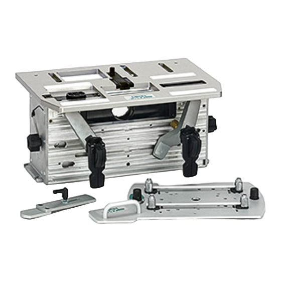
FMT PRO Appendix II
Jig Adjustments
1
2
1
4
3
2
61
Advertisement
Table of Contents

Related Manuals for Leigh FMT Pro


Summary of Contents for Leigh FMT Pro
- Page 1 If your router shaft and bit are not perpendicular to the The left example shows the clamp plate should be adjusted in router sub-base and the Leigh Sub-Base, then the bit will not be toward the jig body ➀ . The right example shows the clamp square to the Jig Table (nor parallel to the Clamp Plate).
- Page 2 Appendix II Frame Mortise & Tenon Jig User Guide JIG ADJUSTMENTS A2-5 Table Clamp Setting The setting for this is factory pre-set A2-6 Sight Position The sight position is factory set. If you using a torque tool. Should you need to adjust the pressure, lock ever need to reset it here’s how.
Need help?
Do you have a question about the FMT Pro and is the answer not in the manual?
Questions and answers