Table of Contents
Advertisement
Quick Links
This thermostat is compatible with most HVAC systems, including the following:
24VAC systems Note: requires both the 24R and 24C (common) wires
Standard gas/oil/electric heating systems
o
o
Heat Pump systems:
o
o
o
Do NOT use for line voltage controls (120/240VAC)
Stop!
Before removing your existing thermostat do the following:
1.
Take a picture of the original wires and terminal connections
2.
Label the wires with the terminal markings on the old thermostat
3.
Record old thermostat terminals and the wire color connected to them below
Standard HVAC System Wiring
Terminal
Meaning
Marking
24VAC Common
C
24VAC Return
R
G
Fan
W or W1
Heat stage 1
Y or Y1
Cool stage 1
Heat stage 2
W2
Cool stage 2
Y2
Heat Pump HVAC System Wiring
Meaning
Terminal
Marking
C
24VAC Common
24VAC Return
R
Fan
G
Aux Heat
W or W1
Compressor stage 1
Y or Y1
Change Over Valve
O (or B*)
Y2
Compressor stage 2
* if you have a terminal marked "B" with a brown wire attached to it, that means you have a
changeover (C/O) with heating type heat pump system. Be sure to set the change over
type in the Installer Settings menu to C/O Type: w/Heat. Otherwise leave it set to
w/Cool.
DCN: 140-01773-03
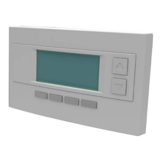
Installation Guide
Model TZ45R
Z-Wave Thermostat
1 stage heating and cooling
2 stage heating and cooling
1 stage heating and cooling
2 stage heating and cooling
nd
rd
2
or 3
stage Auxiliary heating (heat strips)
Typical Wire Color
May be different!!!
Take a picture!
Blue
Red
Green
White
Yellow
Orange
Black
Typical Wire Color
May be different!!!
Take a picture!
Blue
Red
Green
White
Yellow
Orange (brown*)
Black
Record the old thermostat
wire color that was connected
to the terminal
Record the old thermostat
wire color that was connected
to the terminal
Page 1
Advertisement
Table of Contents

Subscribe to Our Youtube Channel
Related Manuals for RCS Technology TZ45R


Summary of Contents for RCS Technology TZ45R
- Page 1 Installation Guide Model TZ45R Z-Wave Thermostat This thermostat is compatible with most HVAC systems, including the following: 24VAC systems Note: requires both the 24R and 24C (common) wires Standard gas/oil/electric heating systems 1 stage heating and cooling 2 stage heating and cooling ...
-
Page 2: Standard Gas/Electric Hvac System Wiring
Standard Gas/Electric HVAC System Wiring Thermostat back Optional 24R Connection for single transformer HVAC Systems RC and RH are jumpered together on thermostat board. Cut RC/RH jumper JP1 for separate heating & cooling transformers Cooling 24V 24RC 24VAC Com 24RH 24V Heating Cooling stage 1 Heating stage 1... -
Page 3: Heat Pump Hvac System Wiring
Heat Pump HVAC System Wiring Thermostat back For Heat Pump systems, connect the 24R connection to either the 24RC or 24RH Cooling 24V 24VAC Com 24RC 24RH 24V Heating Cooling stage 1 Aux Heating W2/O Cooling stage 2 Change Over Valve Remote Sensor 2 Remote Sensor 1 Remote Sensor 2... -
Page 4: Installation & Setup
INSTALLATION SETUP Before operating the system, the HVAC System Type must be setup in the Installer Settings/System Settings/Mechanical Settings Menu! Default Settings: The HVAC System Type is default set for a Gas/Electric system with Gas Heat Fan type. If this matches the HVAC system the thermostat is connected to, then no further setup is required. -
Page 5: Hvac System Setup
HVAC System Setup In the Installer Settings main menu, us the down arrow button to scroll down to the System Settings menu item and press Select. System Settings Menu screen System Settings Mechanical Settings Sched Enable Recovery Enable H/C Delta Done Select Select the Mechanical Settings menu item and press Select. -
Page 6: Installer Settings Menu Items
2nd Stage Heat Enables the 2nd Stage Heating operation Options: Y or N Default: N Aux Heat (if Type=HP) Enables Auxiliary Heat (heat strips) operation. Options: Y or N Default: Y 2nd Stage Cool Enables the 2nd Stage Cooling operation Options: Y or N Default: N Other Installer Settings... - Page 7 Options: 1 to 8 degrees Default: 1 Heating Delta Stage 1 OFF Sets the delta from setpoint that stage 1 heating stops. Stage 1 turns off at setpoint + Delta Stage 1. Options: 0 to 8 degrees Default: 0 Heating Delta Stage 2 ON Sets the delta from setpoint that stage 2 heating starts.
- Page 8 Remote Sensors RS1 Type Specifies the thermistor sensor temperature curve type Options: Curve A, Type 2, Type 3 Default: Type 3 RS2 Type Specifies the thermistor sensor temperature curve type Options: Curve A, Type 2, Type 3 Default: Type 3 RS2 Location Selects RS2 installed location as indoor sensor or outdoor sensor Options: IN (indoor) or OUT (outdoor) Default: IN...
- Page 9 Installer Settings Summary Setting Range Default Display Lock Y or N Locks out front buttons Service Mode Submenu Test Mode Y or N Reduces delays for testing System Settings Submenu Mechanical Settings Submenu Sys Type Std or HP Fan Type Gas or Elec C/O Type w/Heat or w/Cool...
-
Page 10: Z-Wave Thermostat
Operation Guide Model TZ45R Z-Wave Thermostat Main Thermostat Screen Room Temperature Backlite Display Setpoints Temperature Setting 4:30 PM Warmer SYS OFF 72 H ECON HOLD 75 C NO MSG Cooler COOL AUTO MENU HOLD MODE Menu Run/Hold Mode Selection Selection... -
Page 11: Setting The Heating Or Cooling Temperature Setpoint
Setting the heating or cooling temperature setpoint Sys Off Press a button to go to the setpoint change screen HEAT AUTO MENU MODE HOLD Press the up or down arrow buttons to Setpoint change screen set the desired temperature setpoint HEATING SETPOINT Raise Temperature Lower Temperature... -
Page 12: Setting The System Mode: Off, Heat, Cool, Auto
Setting the System Mode: Off, Heat, Cool, Auto 4:30 PM Sys Off HEAT AUTO MENU MODE HOLD Press Mode button to change system mode System Mode change screen SYSTEM MODE Press the UP or HEATING COOLING DOWN buttons AUTO MODE button Done MODE to select the... -
Page 13: System Status Indicators
Setting Fan Mode and System Status Indicators 4:30 PM System Sys Off Status Indicators Filter HEAT AUTO MENU MODE HOLD Press the Fan button to change the Fan mode AUTO FAN: Fan automatically operated by the HVAC system. FAN ON: Manual Fan mode. -
Page 14: Menu Selection
Menu Selection 4:30 PM Sys Off HEAT AUTO MENU MODE HOLD Press Menu button to go to the main menu screen Menu Selection Energy Usage Use the Utility Setup UP/DOWN Messages Schedules buttons to select the desired menu Done Select item Press DONE to go back to Press SELECT to go to the... -
Page 15: User Settings Menu Items
as per that days schedule stored in the thermostat. “Hold” mode stops schedule operation and holds the current setpoints until changed manually or by network commands. The Schedules Screen gives you the option of setting a custom setback schedule or to load one of two preset schedules. - Page 16 Set Clock: The Set Clock screen allows you to set the Thermostat’s internal clock. Set Clock To set the Time and Date, move the cursor with the navigation Time 08:00 AM arrows until the data you want to change is highlighted. Date 01/01/11 Using the + and –...
-
Page 17: Zwave Install
Sensor Calibration Internal (75) Remote 1 n/a Remote 2 n/a Outside Press to refresh Done Backlite/Display: Go to the Backlite/Display settings screen. This menu allows you to set the backlight timeout period and adjust the display contrast. Backlite Timeout: Sets the time from last button press that the backlite will timeout and turn off. -
Page 18: Thermostat Info Screen
Thermostat Info Screen Thermostat Info TZ45R Ver 02.02.29 Press and Hold Setup button ZVER: 2.16 ZNID: 001 ZHID: 00.00.07.76 to go to the HVAC system System Type: Standard Fan Type: setup screen Done Status Setup Setup Button (not labeled on screen) To setup the thermostat to work with your HVAC system, press and hold the “Setup”... -
Page 19: Remote Sensors
Remote Sensors The thermostat has two remote temperature sensor inputs. Remote Sensor RS1. When connected, the thermostat will use the RS1 remote sensor instead of the internal sensor. Temperature displayed will be the RS1 temperature. Remote Sensor RS2. Selectable Indoor or Outdoor Sensor type. RS2 can be selected to be an indoor remote sensor or an outdoor remote sensor in the Installer Settings Remote Sensors menu item. -
Page 20: Z-Wave® Installation
Z-Wave® Installation Z-Wave controllers from various manufacturers may support the Z-Wave Thermostat General V2 Device class used by the RCS Z-WAVE Thermostat. The following procedure will allow the thermostat to be added to a Z-Wave network. General Programming Procedure (for controllers supporting the thermostat device class): Set your primary controller to Include, Add or Install mode, to add the thermostat as a node on your network (see your controller’s user manual for... - Page 21 FCC/IC INFORMATION TO USER This device complies with Part 15 of the FCC Rules. Operation is subject to the following two conditions: (1) This device may not cause harmful interference, and (2) This device must accept any interference received, including interference that may cause undesired operation.
Need help?
Do you have a question about the TZ45R and is the answer not in the manual?
Questions and answers