Table of Contents
Advertisement
This thermostat is compatible with most HVAC systems, including the following:
24VAC systems Note: requires both the 24R and 24C (common) wires
Standard gas/oil/electric heating systems
o
o
Heat Pump systems:
o
o
o
Do NOT use for line voltage controls (120/240VAC)
Stop!
Before removing your existing thermostat, be sure to label the
wires with the terminal markings on the old thermostat and record them
below
.
Standard HVAC System Wiring
Terminal
Meaning
Marking
C
24VAC Common
R
24VAC Return
G
Fan
W or W1
Heat stage 1
Y or Y1
Cool stage 1
W2
Heat stage 2
Y2
Cool stage 2
Heat Pump HVAC System Wiring
Terminal
Meaning
Marking
C
24VAC Common
R
24VAC Return
G
Fan
W or W1
Aux Heat
Y or Y1
Compressor stage 1
O (or B*)
Change Over Valve
Y2
Compressor stage 2
* if you have a terminal marked "B" with a brown wire attached to it, that means you have a
changeover (C/O) with heating type heat pump system. Be sure to set the change over
type in the Installer Settings menu to C/O Type: w/Heat. Otherwise leave it set to
w/Cool.
DCN: 140-02034-03
Installation Guide
Model TZ45A
Z-Wave Thermostat
1 stage heating and cooling
2 stage heating and cooling
1 stage heating and cooling
2 stage heating and cooling
nd
rd
2
or 3
stage Auxiliary heating (heat strips)
Typical Wire Color
Blue
Red
Green
White
Yellow
Orange
Black
Typical Wire Color
Blue
Red
Green
White
Yellow
Orange (brown*)
Black
Record the old thermostat wire
connections and terminal
marking here
Record the old thermostat wire
connections and terminal
marking here
Page 1
Advertisement
Table of Contents

Subscribe to Our Youtube Channel
Related Manuals for RCS Technology TZ45A


Summary of Contents for RCS Technology TZ45A
-
Page 1: Installation Guide
Installation Guide Model TZ45A Z-Wave Thermostat This thermostat is compatible with most HVAC systems, including the following: 24VAC systems Note: requires both the 24R and 24C (common) wires Standard gas/oil/electric heating systems 1 stage heating and cooling 2 stage heating and cooling ... -
Page 2: Hvac System Setup
INSTALLATION HVAC System Setup The thermostat requires that you setup the type and configuration of your HVAC system for proper operation. This is done in the Thermostat Info screen Setup button or the Installer Settings screen on the thermostat. The Installer Settings is a hidden screen. To access it, press the main menu button and when the main menu screen appears, press and hold the middle two buttons for 5 seconds. -
Page 3: Installer Settings Menu Items
thermostat connects to help determine this. If the original system had an orange wire connected to an “O” terminal, then you have a “changeover with cool” system. If you have a brown wire connected to the “B” terminal, then you have a “change over with heat” system. - Page 4 Heating Delta Stage 1 ON Range: 1 to 8 degrees Default: 1 Sets the delta from setpoint that stage 1 heating starts. Heating Delta Stage 1 OFF Range: 0 to 8 degrees Default: 0 Sets the delta from setpoint that stage 1 heating stops. Stage 1 turns off at setpoint + Delta Stage 1.
-
Page 5: Installer Settings Summary
ON time is set to a value greater than 0, an additional “Cycler” FAN mode is present when pressing the FAN button. Fan ON Time Range: 0-120 minutes Default: 0 (=OFF) Fan OFF Time Range: 10-120 minutes Default: 10 Restore Defaults Range: Yes, No Default: No Restores all settings to factory defaults. -
Page 6: Standard Gas/Electric Hvac System Wiring
Standard Gas/Electric HVAC System Wiring Optional 24R Connection for single transformer HVAC Systems RC and RH are jumpered together on thermostat board. Cut RC/RH jumper JP1 for separate heating and cooling transformers 24V R Cooling 24RC 24V Com 24RH 24V R Heating Cooling stage 1 Heating stage 1 W2/O... -
Page 7: Heat Pump Hvac System Wiring
Heat Pump HVAC System Wiring Optional 24R Connection for single transformer HVAC Systems RC and RH are jumpered together on thermostat board. Cut RC/RH jumper JP1 for separate heating and cooling transformers 24V Com 24V R Cooling 24RC 24RH 24V R Heating Aux Heating Compressor stage 1 W2/O... -
Page 8: Z-Wave Thermostat
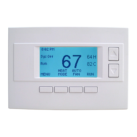
Operation Guide Model TZ45A Z-Wave Thermostat Main Thermostat Screen Room Temperature Backlite Display Setpoints Temperature Setting Warmer Sys Off Cooler HEAT AUTO MENU MODE HOME Menu Home/Away Mode Selection Selection Fan Mode Heating/Cooling Mode Selection Selection Minimized Display (displayed after screen timeout... -
Page 9: Setting The Heating Or Cooling Temperature Setpoint
Setting the heating or cooling temperature setpoint Sys Off Press a button to go to the setpoint change screen HEAT AUTO MENU MODE HOME Press the up or down arrow buttons to Setpoint change screen set the desired temperature setpoint HEATING SETPOINT HEATING SETPOINT Raise Temperature... -
Page 10: Setting The System Mode: Off, Heat, Cool, Auto
Setting the System Mode: Off, Heat, Cool, Auto Sys Off HEAT AUTO MENU MODE HOME Press Mode button to change system mode System Mode change screen SYSTEM MODE Press the UP or HEATING COOLING DOWN buttons AUTO MODE button Done MODE to select the desired system... -
Page 11: System Status Indicators
Setting Fan Mode and System Status Indicators System Sys Off Status Indicators Filter HEAT AUTO MENU MODE HOME Press the Fan button to change the Fan mode AUTO FAN: Fan automatically operated by the HVAC system. FAN ON: Manual Fan mode. Fan stays on until mode is changed back to Auto. Optional Fan Mode Fan Cycler. -
Page 12: Menu Selection
Menu Selection Sys Off HEAT AUTO MENU MODE HOME Press Menu button to go to the main menu screen Menu Selection User Settings Use the Away Setpoints UP/DOWN ZWave Install Thermostat Info buttons to select the desired menu Done Select item Press DONE to go back to Press SELECT to go to the... - Page 13 Maint Service: Go to the Maintenance Service Screen. Sets/resets the maintenance timer/alert. The Maintenance Service screen will show the accumulated Heat and Cool runtime hours as well as the Service Interval that will be used to trigger a Maintenance alert. Service interval is 3000 hours.
-
Page 14: Thermostat Info
Changeover – if HVAC type = Heat Pump: Changeover with cool or changeover with heat. Press and Hold Status button Thermostat Info Screen Thermostat Info to enter Relay Status screen. TZ45A Ver 1.00.00 ZVER: 2.97 ZNID: 001 ZHID: 00.00.07.76 Press Done button to exit... -
Page 15: Z-Wave® Installation
Z-Wave® Installation Z-Wave controllers from various manufacturers may support the Z-Wave Thermostat General V2 Device class used by the RCS Z-WAVE Thermostat. The following procedure will allow the thermostat to be added to a Z-Wave network. General Programming Procedure (for controllers supporting the thermostat device class): Set your primary controller to Include, Add or Install mode, to add the thermostat as a node on your network (see your controller’s user manual for... - Page 16 INFORMATION TO USER This device complies with Part 15 of the FCC Rules. Operation is subject to the following two conditions: (1) This device may not cause harmful interference, and (2) This device must accept any interference received, including interference that may cause undesired operation.
Need help?
Do you have a question about the TZ45A and is the answer not in the manual?
Questions and answers