Table of Contents
Advertisement
Quick Links
This thermostat is compatible with most HVAC systems, including the following:
24VAC systems Note: requires both the R and C wires unless battery powered.
Standard gas/oil/electric heating systems
o
o
Heat Pump systems:
o
o
o
Do NOT use for line voltage controls (120/240VAC)
The thermostat can be powered by batteries or 24VAC.
Battery Power
The thermostat can be powered by four AA Alkaline batteries. The thermostat will operate
for approximately two years on four AA Alkaline batteries depending on the frequency of
user operations and backlight operation. Always use Alkaline batteries and replace in
complete all four at a time with new batteries.
Z-Wave Operation when Battery Powered
Important Note: If the thermostat is installed on a Z-Wave network, while it is battery
powered, it will not work as a Z-Wave repeater.
24VAC Power
Powering the thermostat with 24VAC power requires both the C wire (24VAC common
wire - typically blue) and the R wire (24VAC hot wire - typically red). If the C wire is not
available, then batteries are required.
Note! If the thermostat is powered from 24VAC, batteries are not required.
Z-Wave Operation when 24VAC powered
If the thermostat is installed on a Z-Wave network while it is 24VAC powered, it operates
as an always-on Z-Wave repeater.
Installation Steps
Remove old thermostat.
Install TBZ500
Set up the thermostat for the HVAC system
Enroll on Z-Wave network
Remove old thermostat
Turn off power. Usually at the heating/cooling system or circuit- breaker panel.
Remove cover of old thermostat to expose the wiring terminals
Take a picture of the wiring terminals! Note: This will help with
troubleshooting later if needed.
Mark the wires attached to the terminals with the wiring labels included
DCN: 140-02338-01 DRAFT 20619
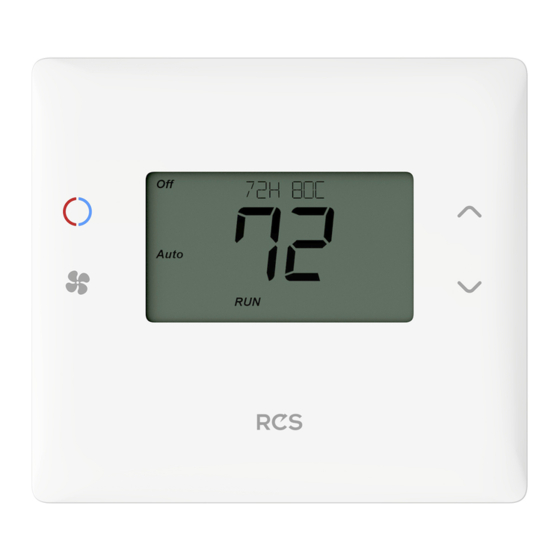
Installation Guide
Model TBZ500
Battery Powered Z-Wave Thermostat
1 stage heating and cooling
2 stage heating and cooling
1 stage heating and cooling
2 stage heating and cooling
nd
rd
2
or 3
stage Auxiliary heating (heat strips)
Page 1
Advertisement
Table of Contents

Subscribe to Our Youtube Channel
Related Manuals for RCS Technology TBZ500


Summary of Contents for RCS Technology TBZ500
- Page 1 Installation Guide Model TBZ500 Battery Powered Z-Wave Thermostat This thermostat is compatible with most HVAC systems, including the following: 24VAC systems Note: requires both the R and C wires unless battery powered. Standard gas/oil/electric heating systems 1 stage heating and cooling 2 stage heating and cooling ...
- Page 2 Caution. Don’t let the wires slip into the wall. *Note: the C wire (24V common) may not be present. Take a Picture! If there is no C wire, the TBZ500 must be powered by batteries. If the C wire is present, you can power the thermostat without batteries Mark the wires according to the terminal markings.
-
Page 3: Mount The Thermostat
To connect dual transformer systems, FIRST REMOVE THE SUPPLIED RH-RC JUMPER. Then connect the heating “R” wire to the RH terminal and the cooling “R” wire to the RC terminal on the thermostat. Single Stage Heat Pump HVAC System Wiring to the Thermostat Connect the wires as marked from the HVAC system to the corresponding terminals on the thermostat back. - Page 4 If the thermostats is battery powered (NO 24VAC C wire connected), install 4 AA batteries into the back of the thermostat. Install batteries Watch polarity! Install the thermostat on to the base. Turn on power to the thermostat. DCN: 140-02338-01 DRAFT 20619 Page 4...
-
Page 5: Standard Gas/Electric Hvac System Wiring
Standard Gas/Electric HVAC System Wiring Standard HVAC System Typical thermostat wiring colors. Thermostat Connection Caution: verify that original wiring Blue matches. Colors may be different. C 24VAC Common R 24VAC Return White W1 Heat Stage 1 Orange W2 Heat Stage 2 Green G Fan Yellow... -
Page 6: Heat Pump Hvac System Wiring
Heat Pump HVAC System Wiring Heat Pump HVAC System Thermostat Connection Typical thermostat wiring colors. Blue Caution: verify that original wiring C 24VAC Common matches. Colors may be different. R 24VAC Return White W1 Aux Heat Orange Changeover Valve Green G Fan Yellow Y1 Compressor Stage 1... -
Page 7: Thermostat Setup
Thermostat Setup The thermostat must be setup for the correct system type and configuration of the HVAC system for proper operation. Preset HVAC System settings The thermostat is preset for the following typical HVAC system configuration: HVAC system type: Standard gas/electric ... - Page 8 Thermostat Menu Screen Menu choices are displayed in the Status Display Line. Press “Select” to enter the selected Use the Up/Down menu buttons to change to the desired Press “Done” to menu item, then exit back to the press “Select” Main Thermostat Screen Selecting the Menu Options...
-
Page 9: Fan Type (For Standard Hvac Systems Only)
Press Select to set. Press Done to exit Fan Type (For Standard HVAC systems only) Fan type depends on the heating system type. For Gas heat: select “GAS”. This is the default setting. For Electric heat: use the Up/Dn arrows to change to “ELECTRIC”. ... - Page 10 To unlock the thermostat, press and hold the FAN button for 5 seconds to access the Setup screen (it’s the only button that works in the lock mode). Access the Advanced Settings Menu (as above) to turn the Display Lock off. Test Mode Range Y or N Default: N...
-
Page 11: Z-Wave Installation
Sets the delta from setpoint that stage 2 heating starts. Heating Stage 2 Off Threshold Range: 0 to 6 degrees Default: 0 Sets the delta from setpoint that stage 2 heating stops. Stage 2 turns off at setpoint + Delta Stage 2. Aux Heat On Threshold Range: 3 to 8 degrees Default: 3... - Page 12 Operation Guide Model TBZ500 Battery Powered Z-Wave Thermostat Main Thermostat Screen Backlit Display Text Display Line Room Temperature Temperature Setting Warmer Heating/Cooling Cooler Mode Selection Fan Mode Selection Battery Compartment Flip over 2xAA or 4xAA Alkaline Batteries Backlight and Button Operation The thermostat backlight is normally set to go out after 20 seconds of no button presses to conserve battery power.
-
Page 13: Setting The System Mode
blinking > System is ON and heating. Minimum Run Time (MRT) delay is active. blinking > System is ON and cooling. Minimum Run Time (MRT) delay is active. Staging Indicators “1” = Stage 1 heating or cooling is ON “2” = Stage 2 heating or cooling is ON “3”... -
Page 14: Setting The Heating Or Cooling Temperature Setpoint
Setting the Heating or Cooling Temperature Setpoint Press either Up or Down arrow button to go to the Setpoint Change screen Setpoint Change screen Press the Up or Down arrow buttons to set the desired Setpoint being changed temperature setpoint Press MODE Raise Temperature button to change... -
Page 15: Setting The Fan Mode
Setting the Fan Mode Press the FAN button to change the Fan mode Fan Modes: Auto: Fan automatically operated by the HVAC system. (normal setting) On: Manual Fan mode. Fan stays on until mode is changed back to Auto, independent of the heating or cooling system operation. -
Page 16: Menu Mode Screen
Menu Mode Screen Menu item display Press “Select” Use the to go to the UP/DOWN selected menu buttons to select item screen the desired menu item Press “Done” to go back to the Thermostat Main Screen Menu Mode options SETUP User preference settings ... -
Page 17: Thermostat Operation
See Installation Guide for more information on System setup and the Advanced Systems Menu Z-WAVE Menu This menu item allows the thermostat to be enrolled to the Z-Wave network. Follow the instructions shown in the Z-Wave® Operation section (page 19) to enroll the Thermostat onto the network. - Page 18 Minimum Off Time (MOT) The thermostat has a Minimum Off Time (MOT) delay after any heating or cooling cycle ends. This delay prevents rapid heating/cooling cycles and also provides “short cycle protection” for the system compressor. This delay may be noticeable when you change a setpoint and it does not respond immediately due to the MOT delay timer preventing the system from restarting.
-
Page 19: Z-Wave ® Operation
® Z-Wave Operation Thermostat Battery Operation: If the thermostat is installed in a Z-Wave network while powered by batteries, it will be enrolled as a Z-Wave FLiRs type device. This is a power saving mode that conserves the batteries by keeping the radio asleep most of the time. However, in this mode, the thermostat does not act as a repeater/router in the Z-Wave network. - Page 20 FCC/IC INFORMATION TO USER This device complies with FCC part 15 FCC Rules. Operation is subject to the following two conditions: This device may not cause harmful interference and This device must accept any interference, including interference that may cause undesired operation of the device.
Need help?
Do you have a question about the TBZ500 and is the answer not in the manual?
Questions and answers