Table of Contents
Advertisement
Quick Links
Advertisement
Table of Contents

Related Manuals for Surface Concept HVPS-HC


Summary of Contents for Surface Concept HVPS-HC
- Page 1 19“ HVPS-HC Module 1Channel/2Channel (Release R014) Manual...
- Page 2 Germany User Manual for the 19” HVPS-HC Module 1Channel/2Channel phone: +49 6131 62716 0 Release: R014 fax: +49 6131 62716 29 Manual Version 2.0 email: info@surface-concept.de web: www.surface-concept.de Printed on 2020-07-14 19” HVPS-HC Module R014 Manual | Surface Concept GmbH...
-
Page 3: Table Of Contents
4 Device Layout & Operation ....................9 4.1 Device Layout ........................9 4.2 General Device Operation ................... 10 4.3 Schematic Layout of the 19” HVPS-HC Module R014 ........11 5 List of Figure ........................... 13 19” HVPS-HC Module R014 Manual | Surface Concept GmbH... - Page 4 19” HVPS-HC Module R014 Manual | Surface Concept GmbH...
-
Page 5: Introduction
2.1 General Information This manual is intended to assist users in the installation, operation and maintenance of Release Version 014 of the 19” HVPS-HC Module. It is divided into 5 chapters. 2.2 Safety Instructions Please read this manual carefully before performing any electrical or electronic operations and strictly follow the safety rules given within this manual. -
Page 6: General Overview
2.3 General Overview The Surface Concept 19” HVPS-HC Module R014 is a high voltage module especially designed for the Surface Concept 19” Basic Unit, a modular supply system. The 19” HVPS-HC Module R014 comes as a 1 channel/2 channel version which provides one/two separate high voltages with a fixed polarity. -
Page 7: Introduction
3.1 Initial Inspection Visual inspection of the system is required to ensure that no damage has occurred during shipping. If there are any signs of damage, please contact SURFACE CONCEPT immediately. Please check the delivery according to the packing list (see Table 1) for completeness. - Page 8 • Install the 19” HVPS-HC Module R014 into a free slot of the 19” Basic Unit (if not already installed). • Use SHV cables to connect to your application. Finish the complete cabling of the 19” HVPS-HC Module R014 before switching on the 19”...
-
Page 9: Device Layout & Operation
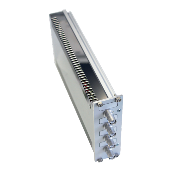
HV channel. (Example for an output voltage with positive polarity.) Figure 2: Layout of the 19” HVPS-HC Module R014 (exemplary comfiguration with a negative output polarity on channel 1 and a positive output polarity on channel 2). 19” HVPS-HC Module R014 Manual | Surface Concept GmbH... -
Page 10: General Device Operation
After switching on the 19” Basic Unit, the display shows the “Surface Concept” animated logo, while the device is scanning for the 19” HVPS-HC Module R014 and its specific settings. This can take up to several seconds. If the 19” Basic Unit is ready for operation, it switches into the standby mode and shows an empty... -
Page 11: Schematic Layout Of The 19" Hvps-Hc Module R014
4.3 Schematic Layout of the 19” HVPS-HC Module R014 Figure 6 shows the schematic layout of the 19” HVPS-HC Module R014 and especially the layout of the HV outputs. An internal controller measures the output voltage and regulates it to the nominal value entered by the user or set as default value within the device. - Page 12 19” HVPS-HC Module R014 Manual | Surface Concept GmbH...
-
Page 13: List Of Figure
Figure 5: Operation mode – voltage adjustment........................... 10 Figure 6: Schematic layout of the 19“ HVPS-HC Module R014 exemplary in the connection layout with a positive output polarity for HV channel 1 and a negative output polarity for HV channel 2............11... - Page 14 This declaration does not represent a commitment to features or capabilities of the instrument. The safety notes and regulations given in the product related documentation must be observed at all times. 19” HVPS-HC Module R014 Manual | Surface Concept GmbH...
Need help?
Do you have a question about the HVPS-HC and is the answer not in the manual?
Questions and answers