
Subscribe to Our Youtube Channel
Related Manuals for Kenmore PG-40407S0LF-1


Summary of Contents for Kenmore PG-40407S0LF-1
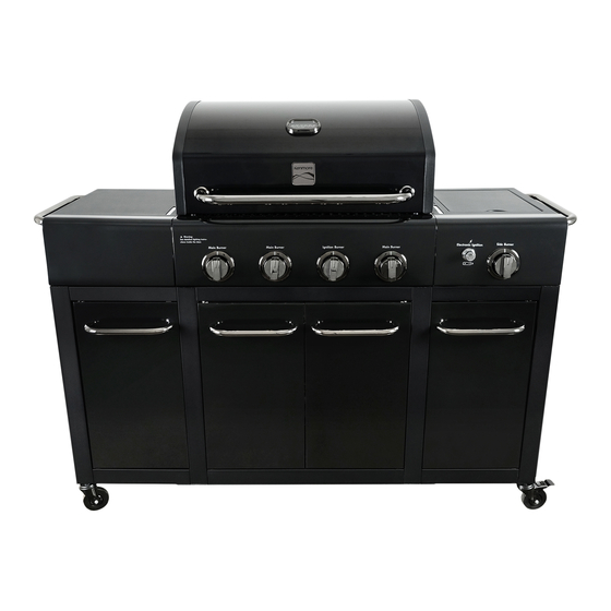
- Page 1 Use & Care Guide Manual de Uso y Cuidado English / Español Kenmore ® Liquid Propane Gas Grill Parrilla a gas de propano lí quido M odel/Modelo: PG-40407S0LF-1 Item No.: 1422186 P/N 407P0015 ®...
-
Page 2: For Your Safety
Installation Safety Precautions DANGER • Please read this User’s Manual in its entirety before using the grill. • Failure to follow the provided instruction can result in If you smell gas: seriously bodily injury and/or property damage. • Some parts of this grill may have sharp edges. Please wear suitable protective gloves. -
Page 3: Table Of Contents
. . 2 Safety Symbols . . . harm. For more information go to Kenmore Grill Warranty ..4 www.P65Warnings.ca.gov Use and Care ..5-11 Parts List . -
Page 4: Kenmore Grill Warranty
WARRANTY KENMORE LIMITED WARRANTY WITH PROOF OF SALE: the following warranty coverage applies when this appliance is correctly installed, operated and maintained according to all supplied instructions. Note: Consumer is responsible for Shipping & handling of all warranty replacement parts. -
Page 5: Use And Care
LP Cylinder USE AND CARE • The LP cylinder used with your grill must meet the following requirements: DANGER • Use LP cylinders only with these required measurements: 12" (30.5cm) (diameter) x 18" (45.7 cm) (tall) with 20 lb. (9 kg.) Capacity maximum. - Page 6 LP Tank Exchange Connecting Regulator To The LP Tank • Many retailers that sell grills offer you the option of replacing 1. LP tank must be properly secured onto grill. (Refer to your empty LP tank through an exchange service. Use only those assembly section.) reputable exchange companies that inspect, precision fill, test 2.
- Page 7 Leak Testing Valves, Hose and Regulator 1.Turn all grill control knobs to OFF. 2.Be sure regulator is tightly connected to LP tank. 3.Completely open LP tank valve by turning OPD hand wheel counterclockwise. If you hear a rushing sound, turn gas off immediately.
- Page 8 Safety Tips WARNING ▲ Before opening LP cylinder valve, check the coupling nut for tightness. ▲ When grill is not in use, turn off all control knobs and LP cylinder For Safe Use of Your Grill and to Avoid Serious valve.
- Page 9 Burner Flame Check WARNING • Remove cooking grates and heat diffusers. Light burners, turn knobs from HI to LO. You should see a smaller flame in LO position than seen on HI. Perform burner flame check Turn controls and gas source or tank OFF on searing burner, also.
- Page 10 • Stainless steel surfaces: To maintain your grill’s high quality Storing Your Grill appearance, wash with mild detergent and warm soapy water and wipe dry with a soft cloth after each use. Baked-on grease •Clean cooking grates. deposits may require the use of an abrasive plastic cleaning •Store in dry location.
- Page 11 Food Safety Food safety is a very important part of enjoying the outdoor cooking experience. To keep food safe from harmful bacteria, follow these four basic steps: Clean: Wash hands, utensils, and surfaces with hot soapy water before and after handling raw meat and poultry. Separate: Separate raw meats and poultry from ready-to-eat foods to avoid cross contamination.
-
Page 12: Parts List
PARTS LIST Description Part Number Description Part Number Side Burner Lid 407F0100Z Drip Cup Clip 40800131 Side Burner Grid 40800119 Drip Cup 40800026 Side Burner Base 40800063 Middle Panel, Left and Right Cart 41600049Z Side Burner 40800121 Bottom Panel, Left and Right Cart 407F0038Z Igniter Wire, Side Burner 40800120... -
Page 13: Parts Diagram
PARTS DIAGRAM... -
Page 14: Before Assembly
BEFORE ASSEMBLY NOTICE: Once you have unpacked the grill according to the STOP SHEET instructions, check all grill parts against the pictures on this and the following two pages. If you parts are missing or damaged, call 1-888-287-0735. M - F 8:00 - 5:00 PACIFIC. - Page 15 BEFORE ASSEMBLY...
- Page 16 BEFORE ASSEMBLY...
-
Page 17: Assembly
ASSEMBLY CAREFULLY READ AND PERFORM ALL ASSEMBLY INSTRUCTIONS ON THE FOLLOWING PAGES. Tools Required: Adjustable wrench (not provided) Screwdriver (not provided) The following hardware is provided in blister pack for convenient use. M4x10 Screw M6X15 Hex Screw Qty: 45pcs Qty: 24 pcs M6x15 Screw... - Page 18 Bottom Rails to Leg Frames (1) IMPORTANT - Assemble grill cart on an even, flat surface. Use a level to confirm that surface is even and flat. - For ease of cart assembly Leg Frames and Bottom Rails are numbered. - Unless instructed otherwise, securely tighten all screws in each assembly step before proceeding to the next step.
- Page 19 Bottom Rails to Leg Frames (2) □ Use (8) M6x15 Hex Screws to attach C21(No.4 Right Cart Bottom Back Rail) and C20(No.3 Right Cart Bottom Front Rail) to C14(No.4 Leg Frame) as shown. Do not fully tighten screws yet. (A) □...
- Page 20 Casters to Cart □ Used Wrench to screw 4 Casters into corresponding position as shown.
- Page 21 Bottom Panels □ Used Pre-assembled (2) M4x10 Screws on the base to attach Door Magnets Box to the Middle Cart Bottom Panel as shown. (A) □ Lay the Middle Cart Bottom Panel onto the No.2 and No.3 Leg Frames. ( □...
- Page 22 Side Door Magnets, Top Front Rails to Leg Frames □ Used (4) M4x10 Screws to attach Side Cabinet Door Magnet to Bottom Panel, Left and Right Cart as shown.(A) □ Used (4) M4x10 Screws to attach C18(Right Cart Top Front Rail)to the No.3 and No.4 Leg Frames as shown.(B) □...
- Page 23 Door Rail, Left and Right Cart Middle Panels □ Used (4) M4x10 Screws to attach the C4(Door Rail) to the top of the No.2 Leg Frame and No.3 Leg Frame as shown.(A) □ Place B18(Middle Panel, Left and Right Cart and B18(Middle Panel, Left and Right Cart) onto pre-install M4 Screws as shown.(B) NOTE: DO NOT fully tighten down the screws.
- Page 24 Cart Doors □ Remove the (2) M5x15 Screws pre-installed to each door handle and use then to attach a door handle to each door as shown.(A) □ Insert the door bottom pin into the hole in the cart bottom front rail. Push down the door top pin, align it with the hole in the cart top front rail, and release pin so that it inserts in hole as shown.(B) □...
- Page 25 Back Panel and Tank Baffle □ Clip the Back Panel into (4) Pre-installed M4x10 Screws as shown. Tighten all the Screws.(A) □ Use (2) M4x10 Screws to attach Tank Baffle to Back Panel and Middle Cart Bottom Panel as shown. (B) M4X10 Screw Qty: 2 pcs...
- Page 26 Grill Head to Cart □ This step requires two people to lift and position grill head onto middle cart. □ Remove the tie wraps securing the regulator hose to the underside of the grill head. Pull the hose and igniter wires out to the side of the grill head.
- Page 27 Left Side Shelf □ Attach Side Shelf Handle to Fascia Left Side Shelf with (2) Pre-installed M6x15 Screws and (2) Pre-installed M6 Compression Washers as shown.(A) □ Attach Left Side Shelf to the cart with (2) M4x10 Screws as shown. (B) Note: (Make sure holes on side shelf align with the holes on cart.).
- Page 28 Right Side Shelf □ Use (2) M5x12 Screws; (2)M5 Flat Washers and (1) M4x10 Screws to attach Right Side Shelf to Fascia Right Side Shelf as shown. Do not fully tighten the screws at this time.(A) □ Attach Side Shelf Handle to Fascia Right Side Shelf with (2) Pre-installed M6x15 Screws and (2) Pre-installed M6 Compression Washers as shown.(B) □...
- Page 29 Side Burner □ Remove the sid e burner grate. Loosen the burner in the side burner shelf (B). To loosen, unscrew and remove two front screws holding side burner in place. (A). Note: Do not loosen electrode screw. □ Remove the 2 pre-installed screws from the valve face and set them aside. (C) □...
- Page 31 Cart Back Panels, Middle Cart Back Rail □ Use (3) M4x10 Screws to attach C2(Back Panel, Left and Right Cart) to Left Cart. Note: Leave the C2(Back Panel, Left and Right Cart)to upper of No.2 Leg Frame unscrew. □ Use (3) M4x10 Screws to attach C2(Back Panel, Left and Right Cart) to Right Cart. Note: Leave the C2(Back Panel, Left and Right Cart)to upper of No.3 Leg Frame unscrew.
- Page 32 Drip Tray and Drip Cup □ Put Drip Tray in the middle of left and right Drip Tray Support as shown.(A) □ Fit drip cup into drip cup clip. Hang drip cup clip at the bottom of drip tray.(B) CAUTION Failure to install drip cup clip and cup will cause hot drip to drip from bottom of grill with risk of fire or property damage.
- Page 33 Regulator Hose Bracket □ Remove cotter key from pin in hose bracket on No.3 Leg Frame and remove pin. Fit the regulator hose into the hose bracket. Secure hose in bracket with bracket pin and cotter key.
- Page 34 Heat Diffusers, Cooking Grates and Warming Rack □ Place heat diffusers over burners. Diffusers will fit in firebox in either direction. Fit tabs in firebox front through slots in diffuser tips. Fit diffuser tips between tabs in firebox rear. □ Place cooking grates onto grate rests at front and rear of firebox. □...
- Page 35 LP Tank and Caster Brakes □ LP tank is sold separately. Use only with an PPD (Overfill Protection Device) equipped LP tank and leak check before attaching to grill and regulator. □ Install LP Tank with Tank Holder and install regulator as shown. □...
-
Page 36: Troubleshooting
EMERGENCIES: If a gas leak cannot be stopped, or a fire occurs due to gas leakage, call the fire department. Problem Possible Cause Prevention/Solution Gas leaking from •Turn off gas at LP cylinder or at source on natural gas systems. •... - Page 37 Troubleshooting (continued) Prevention/Solution Problem Possible Cause Prevention/Solution Burner(s) will not light ELECTRONIC IGNITION: • See Section I of Electronic Ignition System. using igniter. • No spark, no ignition noise. (See Electronic • See Section II of Electronic Ignition System. Ignition •...
- Page 38 Troubleshooting - Electronic Ignition Prevention/Solution Problem Possible Cause Check Item • Battery not installed SECTION I • Check battery orientation. • Install battery (make sure that “+” and “-” properly. No sparks appear at connectors are oriented correctly, with “+” end up and “-”...
Need help?
Do you have a question about the PG-40407S0LF-1 and is the answer not in the manual?
Questions and answers