
Related Manuals for King Canada KC-0712ML


Summary of Contents for King Canada KC-0712ML
- Page 1 7” X 12” VARIABLE SPEED MINI METAL LATHE INSTRUCTION MANUAL MODEL: KC-0712ML COPYRIGHT © 2003 ALL RIGHTS RESERVED BY KING CANADA TOOLS INC.
- Page 2 Warranty does not apply to defects due directly or indirectly to misuse, abuse, negligence or accidents, repairs or alterations and lack of maintenance. KING CANADA shall in no event be liable for death, injuries to persons or property or for incidental, special or consequential damages arising from the use of our products.
- Page 3 GENERAL & SPECIFIC SAFETY INSTRUCTIONS FOR METAL LATHE VOLTAGE WARNING: Before connecting the tool to a power source (receptacle, outlet, etc.) be sure the voltage supplied is the same as that specified on the nameplate of the tool. A power source with voltage greater than that for the specified tool can result in SERIOUS INJURY to the user - as well as damage to the tool.
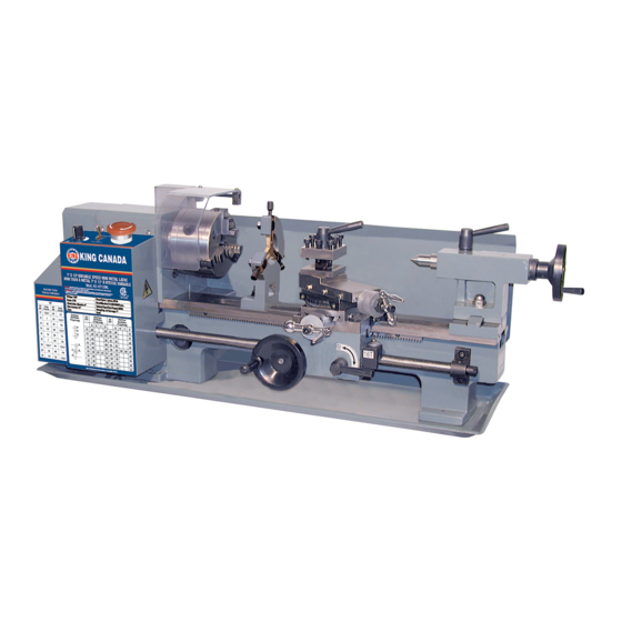
- Page 4 SPECIFICATIONS AND GETTING TO KNOW YOUR LATHE GETTING TO KNOW YOUR LATHE 1. Control box 2. Chuck 3. Top slide 4. 4-way tool post 5. Fixed center 6. Tailstock quill lock handle 7. Tailstock 8. Tailstock quill adjust handwheel 9. Tailstock locking nut 10.
- Page 5 ELECTRICAL CONNECTIONS WARNING! ALL ELECTRICAL CONNECTIONS MUST BE DONE BY A QUALIFIED ELECTRICIAN. FAILURE TO COMPLY MAY RESULT IN SERIOUS INJURY! ALL ADJUSTMENTS OR REPAIRS MUST BE DONE WITH MACHINE DISCONNECTED FROM THE POWER SOURCE. FAILURE TO COMPLY MAY RESULT IN SERIOUS INJURY! POWER SUPPLY WARNING: YOUR METAL LATHE MUST BE CONNECTED TO A 110V, 15-AMP, PROPERLY GROUNDED OUTLET...
- Page 6 OPERATION & REPLACEMENT REPLACEMENT OF CHUCK When replacing the chuck, place a cloth or a piece of wood on the bedway underneath the chuck. This is to avoid damage to the bed way caused by carelessly dropping the chuck. Loosen the three set screws and nuts (A) (only two are shown) as shown in Fig.
- Page 7 OPERATION & REPLACEMENT TOOL POST ADJUSTMENT To adjust the tool post position, you need to loosen the lever (B) shown in Fig.8. After you have finished, be sure to tighten. If you are going to replace the work cutter then you need to loosen the cap screws (A) with one of the hex. keys provided.
Need help?
Do you have a question about the KC-0712ML and is the answer not in the manual?
Questions and answers