
Related Manuals for Velleman-Kit High-Q K6200

Summary of Contents for Velleman-Kit High-Q K6200
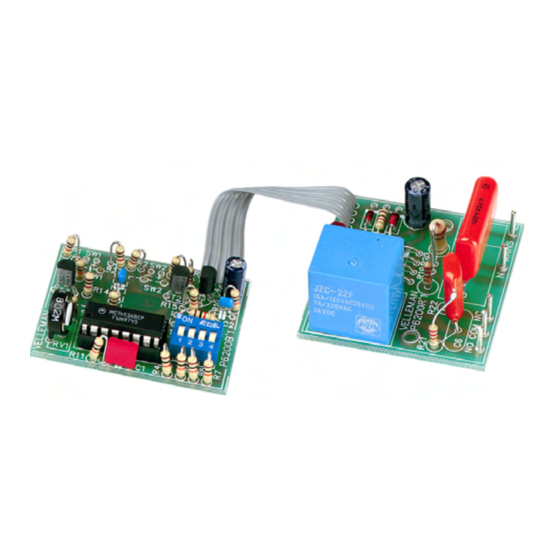
- Page 1 Total solder points: 96 + 43 Difficulty level: beginner 1 advanced 0 TO 60 HOUR START / STOP TIMER K6200 ILLUSTRATED ASSEMBLY MANUAL H6200IP-1...
- Page 2 VELLEMAN NV Legen Heirweg 33 9890 Gavere Belgium Europe www.velleman.be www.velleman-kit.com...
- Page 3 Features & Specifications If you want to have a device switched off after a given time, then this timer is the device you are looking for. Thanks to its big range this timer can be installed just about everywhere, for switching off your TV and HI-FI, the lights in the stairwell, as a security timer for your automatic coffee-maker, as a dark room timer, for mak- ing a short chime signal...
- Page 4 Assembly hints 1. Assembly (Skipping this can lead to troubles ! ) Ok, so we have your attention. These hints will help you to make this project successful. Read them carefully. 1.1 Make sure you have the right tools: A good quality soldering iron (25-40W) with a small tip. •...
- Page 5 Assembly hints 1.3 Soldering Hints : 1- Mount the component against the PCB surface and carefully solder the leads 2- Make sure the solder joints are cone-shaped and shiny 3- Trim excess leads as close as possible to the solder joint REMOVE THEM FROM THE TAPE ONE AT A TIME ! DO NOT BLINDLY FOLLOW THE ORDER OF THE COMPONENTS ONTO THE TAPE.
- Page 6 Construction ASSEMBLY OF THE RELAY MODULE P6200R 1. Diodes. Watch the polarity ! 5. PCB tabs 3. Resistor R... D1 : 1N4148 Mains (2x) D2 : 1N4007 D... CATHODE D3 : 1N4007 D4 : 1N4007 D5 : 1N4007 R18 : 1K (1 - 0 - 2 - B) 2.
- Page 7 Construction & connection 7. Choose your operating voltage 8. Electrolytic Capacitor. Watch the polarity ! For a 24VAC transformer : C5 : 100µF C7 : Jumper wire (see fig 1.0) Fig. 1.0 Required if you are going to control starting C...
- Page 8 Suppressor network 10. Assembly of the suppressor network : C6 : 0,1µF / 400V Fit capacitor C6 vertically, with only one lead soldered. Fig. 2.0 In case you want to suppress the NO contact : Fit R21 (220 ohm 1/2W) also vertically and with only one lead soldered, where after you connect the free ends of the resistor and the capacitor together (see fig.
- Page 9 Tips 11. Tips in the case of noise caused by relays: In case the relays are used to switch alternate current, it may be necessary to suppress them. Suppress resistive loads (bulb, resistor, ...) : Fig. 3.1 Suppress inductive loads (transformer, motor, ...) Fig.
- Page 10 Construction ASSEMBLY OF THE BASIC MODULE P6200B 1. Zenerdiode. Watch the 4. Capacitors. 7. Transistors. polarity ! T1 : BC557B C... T2 : BC557B ZD2 : 15V0 T3 : BC557B CATHODE ZD... C2 : 100nF (104) C3 : 100nF (104) 2.
-
Page 11: Push Button
Construction 10. Trimmer 12. IC, Check the position of R8 : 1K (1 - 0 - 2 - B) R9 : 10K (1 - 0 - 3 - B) the notch! RV... R10 : 10K (1 - 0 - 3 - B) R11 : 10K (1 - 0 - 3 - B) R12 : 10K... - Page 12 Test 14. Test Turn RV1 to its centre position Check that all the switches of the DIP switch are in the OFF state In case the timer was built for connection to the mains, connect the mains voltage to the points marked MAINS, otherwise a transformer must be connected to these points, which can supply 24 to 28VAC at 50mA.
-
Page 13: Other Connections
Other connections 16. Other connections Connecting separate push buttons (fig. 6.0): Connect two push buttons with a normal open contact to the points “+” and “-”, marked SW1 and SW2 respectively. SW2 allows to start the timer while SW1 allows to stop it. Driving through open collector outputs, e.g. - Page 14 Assembly 15. Assembly After the test has been performed successfully you can possibly fit the modules into an adapter housing. First make the holes in the cover as shown in figure 4.0 Fig. 4.0 Connect the mains plug to the MAINS connections Mount the modules into the housing as shown in figure 5.0 After having fitted the cover, check that the LED and the push buttons Fig.
- Page 15 Other connections STOP START P6200B P6200B P6200R P6200R MAINS MAINS 18...24VAC 50mA Fig. 6.0 Fig. 7.0 MAINS...
- Page 16 Settings 17. Setting the desired time See the table for setting the desired time. SW3 settings SW3 settings Time range Time range 2 - 8 sec 13 - 30 min 5 - 15 sec 25 - 60 min 10 - 30 sec 50 - 120 min 25 - 60 sec 100 - 240 min...
- Page 17 18. PCB layout (RELAY MODULE P6200R)
- Page 18 PCB layout (BASIC MODULE P6200B)
- Page 19 Diagram 19. Diagram MAINS STOP START...
- Page 20 Modifications and typographical errors reserved VELLEMAN NV © Velleman nv. Legen Heirweg 33, 9890 Gavere H6200IP - 2004 - ED1 Belgium - Europe 5 4 1 0 3 2 9 3 3 5 1 4 4...
Need help?
Do you have a question about the High-Q K6200 and is the answer not in the manual?
Questions and answers