
Related Manuals for Velleman-Kit WST2579

Summary of Contents for Velleman-Kit WST2579
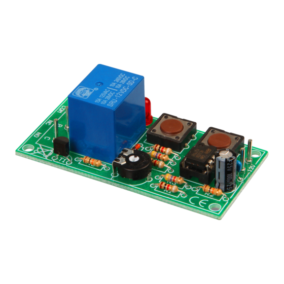
- Page 1 UNIVERSAL START/STOP TIMER K2579 Specifications Relay output with switchover contact. Power supply : 12VDC regulated. Typical active current : 55mA. Relay output : 2A/240V max. Dimensions : 35x70mm / 1.37x2.75"' H2579IP-2...
- Page 2 VELLEMAN NV Legen Heirweg 33 9890 Gavere Belgium Europe www.velleman.be www.velleman-kit.com...
- Page 3 Features & Specifications The K2579 is a basic timer with relay output for time intervals of up to 15 minutes. Set the desired delay with the trimmer. The maximum delay can easily be lengthened and the timer can be stopped and restarted at any time. Features ...
-
Page 4: Assembly Hints
Assembly hints 1. Assembly (Skipping this can lead to troubles ! ) Ok, so we have your attention. These hints will help you to make this project successful. Read them carefully. 1.1 Make sure you have the right tools: A good quality soldering iron (25-40W) with a small tip. ... - Page 5 REMOVE THEM FROM THE TAPE ONE AT A TIME ! DO NOT BLINDLY FOLLOW THE ORDER OF THE COMPONENTS ONTO THE TAPE. ALWAYS CHECK THEIR VALUE ON THE PARTS LIST!
- Page 6 Construction 1. Diode. Watch the polarity ! 3. IC socket. Check the 6. Transistor position of the notch! T1 : BC547B D1 : 1N4148 D... CATHODE 7. Electrolytic Capacitor. IC : 8p. Watch the polarity ! 2. Resistor 4.
- Page 7 Construction 9. Push buttons SW1 : START SW2 : STOP 10. Relay RY : VR15M121C RY... 11. IC. Check the position of the notch! IC : NE555...
-
Page 8: Snubber Network
Connection example 12. Connection example 12V DC 300 mA Snubber network* 100E/1W B or C 220nF/400V *see hook-up and use... - Page 9 Hook-up and use 13. Hook-up and use Connect the unit with a 12VDC regulated power supply as shown in the example. Turn the trimmer all the way counterclockwise. Push the START button. The relay will be activated momentarily. ...
- Page 10 10. PCB layout. 14. PCB layout.
- Page 11 Diagram 15. Diagram POWER +12V 100n 1N4148 VR15M211C DISC BC547 TRIG NE555 100µ...
- Page 12 VELLEMAN NV Legen Heirweg 33, B-9890 GAVERE Belgium (Europe) Modifications and typographical errors reserved - © Velleman nv. H2579P - 2012 - ED2 (rev.2) 5 4 1 0 3 2 9 3 1 1 3 8 4...
Need help?
Do you have a question about the WST2579 and is the answer not in the manual?
Questions and answers
sorry for k2579 timer
The Velleman-Kit WST2579 timer is a universal start/stop timer with a relay output. It allows timing of events from a few seconds up to 15 minutes, extendable to 60 minutes. The timer can be started and stopped at any time using push buttons. It includes an LED status indicator and provides a relay output with a switchover contact rated at 2A/240V max.
This answer is automatically generated
do yyou suppy troubshooter section please