MrCool Universal Series Owner's Manual
Dc inverter / condenser
Hide thumbs
Also See for Universal Series:
- User manual ,
- Service manual (74 pages) ,
- Owner's manual (45 pages)
Table of Contents
Advertisement
Please read this manual carefully before installation and keep it for future reference.
Owner's Manual
Universal
Series
®
DC Inverter / Condenser
MDUO18*
Due to updates and constantly improving performance, the information and instructions within this
manual are subject to change without notice. Please visit www.mrcool.com/documentation to
ensure you have the latest version of this manual.
Version Date: 5-11-21
Thank you for choosing MRCOOL Please read this manual carefully before installation and keep it for future reference.
Copyright © 2021 MRCOOL, LLC
Advertisement
Table of Contents

Related Manuals for MrCool Universal Series


Summary of Contents for MrCool Universal Series
- Page 1 Please visit www.mrcool.com/documentation to ensure you have the latest version of this manual. Version Date: 5-11-21 Thank you for choosing MRCOOL Please read this manual carefully before installation and keep it for future reference. Copyright © 2021 MRCOOL, LLC...
-
Page 2: Table Of Contents
7. Electrical Connection ........ 27 Post Installation Checks ... 32 ....... Maintenance Troubleshooting ........34 Error Codes .......... 36 Unit Maintenance ....... 37 Notice on Maintenance ..... 39 After Sales Services ......42 EU Disposal Guidelines ..43 Page 1 mrcool.com... -
Page 3: Safety Precautions
Before installing, modifying, or servicing the system, the main electrical disconnect switch must be in the OFF position. There may be more than one disconnect switch. If there is another disconnect switch, in addition to the main switch, lock-out and tag this switch with a suitable warning label. mrcool.com Page 2... - Page 4 Product uninstallation and recycling must be performed by a certified technician. If the system has a leak-detection system installed, it should be checked for leaks at least every 12 months. Keep a record of all leak checks for the lifetime of the unit. mrcool.com Page 3...
- Page 5 Please adopt safety protection measures before touching the refrigerant pipe; otherwise injury may occur. Please select the proper copper pipe according to the requirement for pipe thickness. mrcool.com Page 4...
-
Page 6: Appliance Overview
(270) 366-0457. ® 6. When the product is malfunctioning and/or is inoperable, please contact MRCOOL technical support at the aforementioned number, as soon as possible and provide the following information: a. Product Nameplate Contents (model number, cooling / heating capacity, product serial number, factory date) b. -
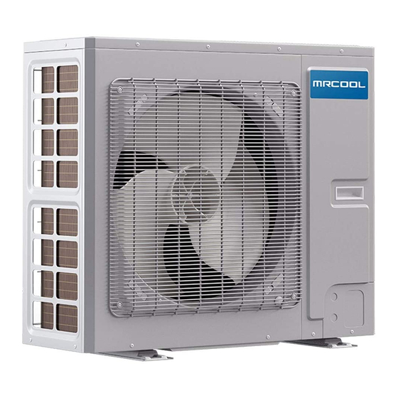
Page 7: Accessories
® No-Vac ® Quick Connect Lineset Gas / Liquid Pipe Assembly Liquid Side Stub Kit To connect the unit with the liquid pipe Gas Side Stub Kit To connect the unit with the gas pipe Fig. 1.1 mrcool.com Page 6... -
Page 8: Operating Range
37 in / 24 in 37 in x 32-1/4 in x 18-1/8 in. 20-7/8 in / 19-1/8 in MDUO18024036 (940 mm / 610 mm) (530 mm / 486 mm) (940 mm x 820 mm x 460 mm) mrcool.com Page 7... - Page 9 42-3/4 in x 53-3/4 in x 14-1/2 in 42-3/4 in / 24-1/2 in 16-7/8 in / 15-1/2 in MDUO18048060 (1085 mm x 1365 mm x 370 mm) (1085 mm / 620 mm) (427 mm / 395 mm) mrcool.com Page 8...
-
Page 10: Unit Installation
Unit is able to be shielded from strong wind. Strong wind may affect the outdoor fan and lead to insufficient air flow volume, thus affecting performance. Unit is away from objects which can generate or amplify noise during operation. Condensate can be safely drained from the unit. mrcool.com Page 9... - Page 11 ≥ 78.74 in ≥ 39.37 in ≤ 100 mm 2000 mm 1000 mm ≥ 7.87 in ≥ 78.74 in ≥ 39.37 in H < H ≤ H > H 200 mm 2000 mm 1000 mm > H Prohibited mrcool.com Page 10...
- Page 12 ≥ 98.43 in ≥ 39.37 in ≤ 250 mm 2500 mm 1000 mm ≥ 11.81 in ≥ 98.43 in ≥ 39.37 in > H H < H ≤ H 300 mm 2500 mm 1000 mm > H Prohibited mrcool.com Page 11...
- Page 13 ≥ 15.75 in 400 mm ≥ 23.62 in 600 mm Fig. 2.3 inches (in) millimeters (mm) ≤ b ≥ 9.84 in (250 mm) H < H ≤ H b ≥ 11.81 in (300 mm) > H Prohibited mrcool.com Page 12...
- Page 14 ≥ 15.75 in 400 mm ≥ 19.69 in 500 mm WALL ≥ 7.87 in 200 mm Fig. 2.4 ≥ 15.75” ≥ 15.75 in 400mm 400 mm ≥ 19.69” ≥ 19.69 in 500mm 500 mm ≥ 11.81 in 300 mm mrcool.com Page 13...
-
Page 15: Outdoor Installation
4 in (101.6 mm) from the ground. Plugs and drainage connector are not recommended if there is an electrical heater on the chassis. Refer to Fig. 2.5 for details. Fig. 2.5 mrcool.com Page 14... -
Page 16: Conventional Line Set Installation
Be extremely careful not to dent or damage the piping while bending them away from the unit. Any dents in the piping will affect the unit’s performance. For installation with a No-Vac® Quick Connect® Line Set, refer to the next section starting on page 24 mrcool.com Page 15... - Page 17 Fig. 2.8 A (Pipe Diameter) Inches Inches Inches ≥1 ≥26 ≥5.91 ≤150 ≥1.3 ≥33 ≥5.91 ≤150 ≤150 ≥1.34 ≥34 ≥5.91 For installation with a No-Vac® Quick Connect® Line Set, refer to the next section starting on page 24 mrcool.com Page 16...
- Page 18 3. After removing burrs from cut pipe, seal the ends with PVC tape to prevent foreign materials from entering the Fig. 2.10 pipe. For installation with a No-Vac® Quick Connect® Line Set, refer to the next section starting on page 24 mrcool.com Page 17...
- Page 19 flaring. Fig. 2.13 PIPING EXTENSION BEYOND FLARE FORM Flare form A = ~1/16 in (1.6 mm) Pipe Fig. 2.14 For installation with a No-Vac® Quick Connect® Line Set, refer to the next section starting on page 24 mrcool.com Page 18...
- Page 20 Cutter bending, place the insulation back on the pipe and secure it with adhesive tape. Cut line Fig. 2.16 For installation with a No-Vac® Quick Connect® Line Set, refer to the next section starting on page 24 mrcool.com Page 19...
- Page 21 Unit Installation Conventional Line Set Installation Replacement Condenser Only Existing Air Handler Fig. 2.17 MRCOOL Universal Series DC Inverter Existing Air Handler in house must be 410 air handler and 410 TXV Bi ow valve must have 410 Accessory copper...
- Page 22 44-48 ft/lbs (60-65 Nm) 52-55 ft/lbs (70-75 Nm) 3/4 in | 19 mm 7/8 in | 22.2 mm 59-63 ft/lbs (80-85 Nm) For installation with a No-Vac® Quick Connect® Line Set, refer to the next section starting on page 24 mrcool.com Page 21...
- Page 23 Refer to Fig. 2.20 on the following page. For installation with a No-Vac® Quick Connect® Line Set, refer to the next section starting on page 24 mrcool.com Page 22...
- Page 24 (Not for No-Vac Quick Connect) MDUO18024036 24.6 ft | 7.5 m ≤31.2 ft | ≤9.5 m 0.32 oz/ft 30 g/m MDUO18048060 For installation with a No-Vac® Quick Connect® Line Set, refer to the next section starting on page 24 mrcool.com Page 23...
-
Page 25: Vac ® Quick Connect ® Installation
Air Handler 52 ft/lb 3/8” 37 ft/lb 3/8” 3/4” 52 ft/lb 3/4” MRCOOL Universal Series DC Inverter Open the stop valve only after connecting the refrigerant lines Connect using precharged A-coil Precharged line set with quick connect with 410 Refrigerant ttings in length 15, 25, 35, 50 feet ⱡFailure to follow the instructions provided could result in severe harm to you, this product, or other property. -
Page 26: Installation Of Drain Pipe
The entire line set, including drain pipe should be wrapped with insulating tape to avoid water returning to the interior. Wrap the insulating tape from bottom to top. The entire line set, including drain pipe should be supported and fixed onto the wall with saddles. MDUO18048060 MDUO18024036 ® Fig. 2.22 mrcool.com Page 25... -
Page 27: Condenser Field Conversion
4 TON SETTING Condenser Main Board NOTE Refer to the Universal Air Handler Installation Manual for Dip Swith Instructions and settings to convert the Universal Air Handler from 3 ton to 2 ton, or 5 ton to 4 ton. mrcool.com Page 26... -
Page 28: Electrical Connection
The wire gauge of the power cord should be sufficiently large. A damaged power cord, or other wires, must be replaced by specialized wires. Wiring work must be done according to national wiring rules and regulations. Wiring terminals should be connected firmly to the teminal board. mrcool.com Page 27... - Page 29 Locate the round terminal conduit. Use a screwdriver to replace it and tighten up the terminal screw, as shown in Fig. 2.29. A. Solid Wire B. Braided Wire Solderless Terminal Fig. 2.28 B Fig. 2.28 A Insulation Layer mrcool.com mrcool.com mrcool.com Page 27 Page 28 Page 28...
- Page 30 Round Terminal Fig. 2.29 Terminal Board Wire For all terminal wiring ( Refer to Fig. 2.30 5. Lead the thermostat wire and power cord through the insulation tube, as shown in Fig. 2.30. Fig. 2.30 mrcool.com Page 29...
- Page 31 However, the indoor fan should operate continuously, which is controlled by the wire controller. NOTE: As for the indoor units, which do not include D, there is no need to connect the D terminals. Fig. 2.31-A mrcool.com Page 30...
- Page 32 The temperature thermostat wire should also be laid along with the right side plate but away from the power cord. Electrical wiring of Single-phase unit: MDUO18024036 Electrical wiring of Single-phase unit: MDUO18048060 mrcool.com mrcool.com Page 31 Page 31...
-
Page 33: Post Installation Checks
Are there any obstacles blocking the air Cooling capacity could be affected if inlet or outlets of the units? there is an obstruction. Have you recorded the length of The refrigerant charging amount refrigerant pipe and the refrigerant cannot be controlled. charge amount? mrcool.com Page 32... - Page 34 If all the above checks have been completed, power on the unit. Make sure the unit runs normally. If the outside temperature is more than 86°F (30°C), heating mode cannot be enabled. If there are any loud and/or abnormal sounds contact MRCOOL Tech Support immediately. ®...
-
Page 35: Maintenance
Too many heat sources in the room. Remove unnecessary heat sources. Filter is blocked or dirty. Replace with a new return lter. Air inlet and outlet of the units have Clear the obstacles and keep the area been blocked. well ventilated. mrcool.com Page 34... - Page 36 NOTICE Check the above items and take appropriate corrective measures. If the air conditioner continues to improperly function, please turn off the air conditioner immediately and contact MRCOOL , or your installing dealer. ® mrcool.com Page 35...
- Page 37 ® electric shock or a fire hazard. 2) DO NOT attempt repairs to the appliance yourself. Improper repair and maintenance can create electric shock and fire hazards. Please contact MRCOOL Tech Support for ® further guidance or a qualified professional for repairs.
-
Page 38: Unit Maintenance
4) Do not use organic solvent to clean the air conditioner. 5) If you need to replace a component, contact a professional to repair the unit with a component supplied by MRCOOL® to ensure the quality. 6) Improper operation may damage the unit, causing electric shock or re. - Page 39 “ON” status at least 8 hours prior to operation to preheat the crankcase of the compressor. 5) Check that the outdoor unit is firmly secured; 6) If problems are detected, contact your local service professional or MRCOOL ® Post-Season Maintenance Checklist 1) Deactivate the main power to the air conditioner.
-
Page 40: Notice On Maintenance
Refrigeration Equipment Checks Ensure all electrical components are compatible with the product and built to the correct specifications. Follow manufacturer maintenance and service guidelines at all times. When in doubt, consult the MRCOOL technical department for assistance. ® If using flammable refrigerants, conduct the following checks: 1) Ensure ventilation machinery and outlets are operating adequately and are not obstructed. - Page 41 flammable atmosphere. The test apparatus must be at the correct rating. 3) Replace components only with parts specified by the manufacturer. Other parts may result in the ignition of refrigerant in the atmosphere from a leak. mrcool.com Page 40...
- Page 42 3) Make sure that cylinder is situated on the scales before recovery takes place. 4) Start the recovery machine and operate in accordance with manufacturer's instructions. 5) DO NOT overfill cylinders. Cylinders should have no more than an 80% volume of liquid charge. mrcool.com Page 41...
-
Page 43: After Sales Services
When oil is drained from a system, it shall be carried out safely. After-Sales Services Any quality issues or other problems encountered with the purchased air conditioner, please contact the local MRCOOL after-sales service department. ® mrcool.com... -
Page 44: Eu Disposal Guidelines
Sell the appliance to certified scrap metal dealers. Special notice Disposing of this appliance in the forest or other natural surroundings endangers your health and is bad for the environment. Hazardous substances may leak into the ground water and enter the food chain. mrcool.com Page 43... - Page 45 ELECTRICIAN and/or HVAC TECHNICIAN: LICENSE #: INSTALLATION DATE: INSTALLATION LOCATION: SERIAL NUMBER: The design and specifications of this product and/or manual are subject to change without prior notice. Consult with the sales agency or manufacturer for details. Copyright © 2021 MRCOOL, LLC...
Need help?
Do you have a question about the Universal Series and is the answer not in the manual?
Questions and answers