MrCool Universal Series Owner's Manual
Hide thumbs
Also See for Universal Series:
- User manual ,
- Service manual (74 pages) ,
- Owner's manual (45 pages)
Table of Contents
Advertisement
Advertisement
Table of Contents

Related Manuals for MrCool Universal Series


Summary of Contents for MrCool Universal Series
- Page 1 Please read this manual carefully before installation and keep it for future reference. Owner’s Manual Universal™ Series Air Handler Thank you for choosing MRCOOL. Please read this manual carefully before installation and keep it for future reference. Copyright © 2019 MRCOOL, LLC...
-
Page 2: Table Of Contents
3. No-Vac® Quick Connect ® Installation..12 4. Condensate Removal ........13 5. Ductwork ............14 6. Electric Heater ..........15 7. Electrical Connection ........16 Post Installation Checks ... 21 Troubleshooting ......23 ....Maintenance and Care EU Disposal Guidelines ....28 Page 1 mrcool.com... -
Page 3: Safety Precautions
CEC (by authorized personnel only.) Contact an authorized service technician for repair or maintenance of the unit. Only use the included accessories and specified parts for installation. Using non-standard parts can cause water leakage, elctrical shock, or fire and may cause the unit to fail. mrcool.com Page 2... - Page 4 Product uninstallation and recycling must be performed by a certified technician. If the system has a leak-detection system installed, it should be checked for leaks at least every 12 months. Keep a record of all leak checks for the lifetime of the unit. mrcool.com Page 3...
- Page 5 Before operating the unit under low temperature, connect it to power for 8 hours. If it is deactivated for a short time, for example, one night, do not cut off the power (this is to protect the compressor). mrcool.com Page 4...
-
Page 6: Appliance Overview
We reserve the right to revise the contents of this manual without notice. 8. If the supply cord is damaged, it must be replaced by MRCOOL, a professional service agent or similarly qualified person in order to avoid damage to the product. -
Page 7: Accessories
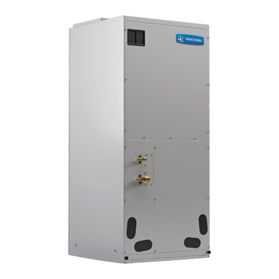
Appliance Overview The Universal Series™ Air Handler offers the perfect combination of superior product quality, operating efficiency, operating sound levels, and value for money. The condensing unit uses the environmentally friendly refrigerant R410A, which is chlorine-free to help prevent damage to the ozone layer. -
Page 8: Unit Dimensions
Appliance Overview Unit Dimensions MDUI18024/MDUI18036 Fig. 1.1 Unit Dimensions (Inches/MM) Width Depth Height 21-1/4in. (540)mm 48-1/4in. (1224mm) 11-5/8in. (295mm) 20in. (508mm) 21-1/4 in. (540mm) mrcool.com Page 7... -
Page 9: Main Parts
Primary Drain Pan Model Cooling capacity (ton) Optional electric heater (kW) 5-20 MDUI18024 / MDUI18036 Motor @ 230V ~, 60Hz Model MDUI18024 / MDUI18036 Unit: inch ( mm) Model Filter size MDUI18024 / MDUI18036 19-5/16×20-5/16× 5/8 (490×516×15) mrcool.com Page 8... -
Page 10: Unit Installation
This product is designed and manufactured to comply with national codes. It is installer’s responsibilities to install the product in accordance with such codes and/or any prevailing local codes/regulations. The manufacturer assumes no responsibilities for equipment installed in violation of any codes or regulations. 4. Replacement Parts... (continued on following page) mrcool.com Page 9... -
Page 11: Installation Location
8 Fig. 2.2 feet/2500mm. and the air handler is not accessible to the general public. Fig. 2.1 mrcool.com Page 10... -
Page 12: Conventional Line Set Installation
Oil Applied (to reduce Copper Piping Torque Wrench friction with the flare nut) Spanner Flare Nut Fig. 2.6 Piping Union Fig. 2.7 Oil Applied (improves air-tight seal) Pipe diameter (inch) Tightening torque (N·m) 15-30 35-40 45-50 60-65 70-75 80-85 mrcool.com Page 11... -
Page 13: No-Vac® Quick Connect ® Installation
NO-VAC™ QUICK CONNECT® LINE SETs allow you to connect indoor and outdoor units simpler, faster and safer. NO-VAC™ QUICK CONNECT® LINE SETs are an�-kink and pre-charged with refrigerant; suitable for most MRCOOL® installa�ons. NO-VAC™ QUICK CONNECT® LINE SETs are a double-sealing system with a unique automa�c safety valve that releases the refrigerant only when the indoor and outdoor equipment is connected and sealed, thus avoiding any risk of leakage. -
Page 14: Condensate Removal
See the following figure for details of a typical condensate line “P” trap. Drain Connection Unit 2” Minimum Flexible Tubing (Hose or Pipe) Fig. 2.8 3” Minimum Positive Liquid Seal (Required) mrcool.com Page 13... -
Page 15: Ductwork
The only heater kits that can be used are HNRd series. Please refer to installation instructions provided with heater kit for the correct installation procedure. WARNING • The electrical characteristics of the air handler, the electric heater kit, and the supply power should be identical. mrcool.com Page 14... - Page 16 9) Replace access panel and check operation. Kit #. Description Kit #. Description HNRd5-D Circuit breaker, 5kW heat strip HNRd15-D Circuit breaker, 15kW heat strip HNRd8-D Circuit breaker, 8kW heat strip HNRd20-D Circuit breaker, 20kW heat strip HNRd10-D Circuit breaker, 10kW heat strip mrcool.com Page 15...
-
Page 17: Electrical Connection
Do not change the length and terminals of the power cables. If you want to change the power cables, please contact MRCOOL’s local service center. Wiring terminals should be connected firmly to the terminal board. Loose connection is not safe. - Page 18 The maximum length is 98 feet (30m). Please select a proper length according to local conditions. Communication cords must not be twisted together. The gauge of signal wire should not be less than AWG18. It’s recommended to use AWG18 power cords as the signal wire. mrcool.com Page 17...
- Page 19 Use a round terminal fastener or clamp to secure the round terminal firmly on the peeled wire end. Locate the round terminal conduit. Use a screwdriver to replace it and tighten the terminal screw (as shown in Fig. 2.10). A. Solid Wire B. Braided Wire Solderless Terminal Fig. 2.10 Jacket / Insulation mrcool.com Page 18...
- Page 20 Refer to Fig. 2.13 on the next page Lead the connection wire and power cord through the insulation tube. Then secure the wires with wire clamps (as shown in Fig. 2.12). Insulation Tube Cord Clamp Fig. 2.12 mrcool.com Page 19...
- Page 21 When connecting the power cord, make sure the phase sequence of the power supply matches with the corresponding terminals, otherwise the compressor will get reversed and operate abnormally. Electrical wiring of Single-phase unit: MDUI18024/MDUI18036 Breaker POWE R 208-230V L1 60Hz Temperature Controller INDOOR UNIT Fig. 2.13 mrcool.com Page 20...
-
Page 22: Post Installation Checks
It may cause air leak, vibration, and Is the panel mounted firmly? condensation. Are there any cracks in the air return It may cause air leak, vibration, and or supply pipe? condensation. mrcool.com Page 21... - Page 23 Operation After Connecting The Power: If all the above steps are complete, power on the unit. If there are any loud and/or abnormal sounds, turn off the unit and contact MRCOOL Tech Support immediately. Verify the unit operates normally under several modes.
- Page 24 Reduce heat source. Filter screen is blocked by dirt. Clean the lter. NOTICE Check the above items and take appropriate corrective measures. If the unit continues to function improperly, immediatey disconnect power and contact MRCOOL or your installation dealer. mrcool.com Page 23...
-
Page 25: Troubleshooting
Indoor fan can be set as “ON” or “AUTO” Indoor unit still After every indoor unit receives "stop" mode. Under “ON” mode, indoor fan runs after signal, fan will keep running. will keep running after switching o the switched o . unit. mrcool.com Page 24... - Page 26 WARNING When abnormalities occur, stop the unit immediately and disconnect power. Contact MRCOOL. If the unit continues to run abnormally, it may damage the unit and cause an electric shock or a fire hazard. DO NOT attempt repairs to the appliance yourself. Improper repair and maintenance can create electric shock and fire hazards.
- Page 27 Bus low-voltage protection Bus high-voltage protection Charge loop error Input voltage error Driver memory chip error ODU jumper cap error NOTICE When the unit is connected with the wired controller, the error code will show simultaneously on it. mrcool.com Page 26...
-
Page 28: Maintenance And Care
First run of the unit should be operated by professional personnel from factory appointed service center. Only factory manufactured accessories can be used on the machine. All the instructions listed in this manual should be followed. Warranty will be automatically voiced if the above requirements are not met. mrcool.com Page 27... -
Page 29: Eu Disposal Guidelines
Selltheappliance to certified scrapmetaldealers. Special notice Disposing of this appliance in the forest or other natural surroundings endangers your health and is bad for the environment. Hazardous substances may leak into the ground water and enter the food chain. mrcool.com Page 28... - Page 30 ELECTRICIAN and/or HVAC TECHNICIAN: LICENSE #: INSTALLATION DATE: INSTALLATION LOCATION: SERIAL NUMBER: The design and specifications of this product and/or manual are subject to change without prior notice. Consult with the sales agency or manufacturer for details. Copyright © 2019 MRCOOL, LLC...
Need help?
Do you have a question about the Universal Series and is the answer not in the manual?
Questions and answers
how to turn up the air handler air flow via dip switches
To adjust the airflow on a MrCool Series air handler using dip switches, refer to the Universal Air Handler Installation Manual for dip switch instructions and settings. This includes conversions such as from 3-ton to 2-ton or 5-ton to 4-ton. The dip switches are used to set the system capacity, which affects airflow. Specific dip switch positions determine the airflow rate by setting the system's tonnage.
This answer is automatically generated