
Related Manuals for Side-Power RC-20U


Summary of Contents for Side-Power RC-20U
- Page 1 Installation & User Manual Radio Remote RC-20U RC-21U RC-22U RC-23U SLEIPNER MOTOR AS P.O. Box 519 N-1612 Fredrikstad Norway www.side-power.com Document id: 5488 Revision: © Sleipner Motor AS 2018...
-
Page 2: Table Of Contents
The radio remote control can control a single bow thruster/windlass or a bow and stern thruster/ windlass combined. The receiver can receive the signals of up to four transmitters/remote con- trols. Remote control kit RC-20U consists of: Receiver: Part no. RCR-2U Transmitter (incl. battery): Part no. RCT-20U Holding bracket for transmitter unit: Part no. -
Page 3: Technical Specifications
Technical specifications Transmitter Receiver Power feed 1x3V battery (type: CR2032) 12V or 24V power source Frequency (MHz) 914-917 MHz 914-917 MHz RF-power <10mW <10mW Operation temp. -10°C / +55°C -15°C / +55°C HxWxD (mm) 107x47x21 83x136x36 Weight (g) Voltage 8-30V Standby power <300mW Load, max... -
Page 4: Receiver Installation
Receiver installation Prior to installation, it is important that the responsible installer reads this guide to ensure necessary acquaintance with this product. WARNING! WARNING! Remote receiver power supply negative lead must be connected to the thrusters`s negative lead. Bow and stern thruster must have common negative. Power to the thruster’s must be switched off during installation! •... - Page 5 Mount the receiver by using the 4 holes. Designed by Checked by Approved by olekr Installation & User Manual, Radio Remote 5488-2-2018 Page 5...
-
Page 6: User Precautions
User precautions • Ensure that you know the location of the main battery switch that disonnects the thruster from all power sources (batteries) so that the thruster/windlass can be turned off in case of a mal- function. • The maximum continues usage time of the electrical thruster is approx. 3 minutes. The electro motor has a built in thermal cut-off switch that will shut it off when overheating and re-engage it when it has cooled down some. -
Page 7: How To Use Rc-20U
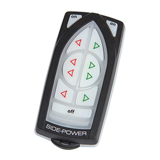
RC-20U Bow + Stern thruster Remote control “ON” Turn boat to Port Turn boat to Starboard Remote control “OFF” Auto-OFF appr. 4 min. Hold for 2 seconds How to use a bow/stern thruster 1. Turn the main power switch for the bow/stern thruster on. Turn on main switch so the receiver has power. -
Page 8: How To Use Rc-21U
RC-21U Windlass Remote control “ON” Turn boat to Port Down Turn boat to Starboard Remote control “OFF” Auto-OFF appr. 4 min. Hold for 2 seconds How to use a bow thruster 1. Turn the main power switch for the bow thruster on. Turn on main switch so the receiver has power. -
Page 9: How To Use Rc-22U
RC-22U Remote control “ON” Windlass 1 Windlass 2 Down Down Remote control “OFF” Auto-OFF appr. 4 min. Hold for 2 seconds How to use a bow/stern windlass 1. Turn the main power switch for the windlass on. Turn on main switch so the receiver has power. -
Page 10: How To Use Rc-23U
RC-23U Bow + Stern thruster Remote control “ON” Turn boat to Port Turn boat to Starboard Remote control “OFF” Auto-OFF appr. 4 min. Hold for 2 seconds Windlass 1 Down Windlass 2 Down Installation & User Manual, Radio Remote 5488-2-2018 Page 10... - Page 11 How to use a bow/stern thruster 1. Turn the main power switch for the bow/stern thruster on. Turn on main switch so the receiver has power. 2. Turn on the transmitter by pushing the transmitter’s two “ON” buttons. The remote system is now activated and then turns off automatically appr.
-
Page 12: Transmitter Led Operation And Alarm Indication
Transmitter LED operation and alarm indication State LED status Alarm status Transmitter ON The yellow LED’s No sound blink each second Buttons activated The yellow LED’s No sound blink fast Pairing mode All LED’s on No sound Connection lost Red LED is blink- 3 beeps from the ing once each buzzer each second... -
Page 13: Electric Diagram
Electric diagram Remember! Cables/wires must be cable tied well. To Thruster To Thruster Control Panel Control Panel STERN To Bow To Stern Thruster Thruster BLACK FUSE Battery 12/24V Remember! Power cables must be connected to the battery as shown. Remaining wires must be cable tied well. -
Page 14: Output Signals Diagram
Output signals diagram RED – Thruster Positive Thruster Bow BLUE – Thruster STBD GREY – Thruster PORT YELLOW – Automatic Mainswitch Enable RED – Thruster Positive Thruster Stern BLUE – Thruster STBD GREY – Thruster PORT YELLOW – Automatic Mainswitch Enable RED - COMMON Windlass Bow BLUE –... -
Page 15: Programming Additional Transmitters/Remote Controls
Programming additional Transmitters/Remote controls Pair Button The original transmitter and receiver have the same factory preset code so that no programming is necessary. When additional transmitters/remote controls are to be used, the additional transmit- ters/remote controls has to be paired with the receiver. Be sure that there is power on the receiver (Green status LED blinking) and that the transmit- ter that should be paired is off. -
Page 16: Replacing Transmitter Battery
Replacing transmitter battery Battery WARNING: Before working on the transmitter, deactivate the transmitter and the receiver (push “OFF” on the transmitter(s)) and turn off the power to the receiver as well as the thruster mainswitch. 1. Open the transmitter case by removing the 3 torque screws. 2. -
Page 17: Dimensions
Dimensions NS-ISO 2768-1 Over t.o.m. f ±0,05 ±0,1 ±0,2 - ±0,05 ±0,1 ±0,3 ±0,5 ±0,1 ±0,2 ±0,5 ±1 ±0,15 ±0,3 ±0,8 ±1,5 120 400 ±0,2 ±0,5 ±1,2 ±2,5 400 1000 ±0,3 ±0,8 ±2 ±4 1000 2000 ±0,5 ±1,2 ±3 ±6 2000 4000 - ±2 ±4... -
Page 18: Safety Information
Safety Information FCC statements Changes or modifications to the equipment not expressly approved by the party responsible for compliance could void the user's authority to operate the equipment. This device complies with Part 15 of the FCC Rules. Operation is subject to the following two conditions: (1) this device may not cause harmful interference, and (2) this device must accept any interference received, including interference that may cause undesired operation. - Page 19 Installation & User Manual, Radio Remote 5488-2-2018 Page 19...
- Page 20 Worldwide sales and service www.side-power.com SLEIPNER MOTOR AS P.O. Box 519 N-1612 Fredrikstad Norway The information given in the document was correct at the time it was published. However, Sleipner Motor AS can not accept liability for any inaccuracies or omissions it may contain.
Need help?
Do you have a question about the RC-20U and is the answer not in the manual?
Questions and answers