Table of Contents
Advertisement
Quick Links
Advertisement
Table of Contents

Related Manuals for Altec ATP-23


Summary of Contents for Altec ATP-23
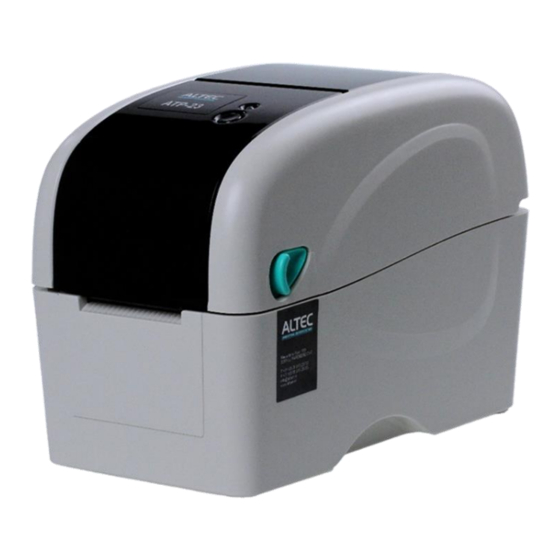
- Page 1 ATP-23 THERMAL TRANSFER / DIRECT THERMAL LABEL PRINTER USER’S MANUAL...
-
Page 2: Table Of Contents
Inhoud Introduction .............................. 3 Product Introduction ........................3 Compliances ............................ 3 Operations Overview ..........................4 Unpacking and Inspection ....................... 4 Printer Overview ..........................5 2.2.1 Front View ........................... 5 2.2.2 Interior View..........................6 2.2.3 Rear View ............................ 7 Setup ................................ 8 Setting Up the Printer ........................ -
Page 3: Introduction
Introduction 1.1 Product Introduction Thank you for purchasing ATP-23 label printer. Although the printer has a small footprint, it delivers reliable, superior performance. This printer provides direct thermal printing at user selectable speed of: 2.0, 3.0, 4.0 or 5.0 ips. -
Page 4: Operations Overview
Operations Overview 2.1 Unpacking and Inspection This printer has been specially packaged to withstand damage during shipping. Please carefully inspect the packaging and printer upon receiving the bar code printer. Please retain the packaging materials in case you need to reship the printer. Unpacking the printer, the following items are included in the carton. -
Page 5: Printer Overview
2.2 Printer Overview 2.2.1 Front View 1. LCD display (Factory option) 2. LED indicator 3. Feed button 4. Paper exit chute 5. Media view window 6. Top cover open lever... -
Page 6: Interior View
2.2.2 Interior View 1. Ribbon access cover 2. Ribbon rewind hub 3. Ribbon rewind gear 4. Print head 5. Ribbon supply hub 6. Gap sensor (receiver) 7. Media holders 8. Media guide 9. Top cover support 10. Black mark sensor 11. -
Page 7: Rear View
2.2.3 Rear View 1. Power switch 2. Power jack socket 3. USB interface 4. USB host (Factory option) 5. RS-232C interface / Ethernet interface (Option) 6. SD card socket Note: * The interface picture is for reference only. Please refer to the product specification for the interface availability. -
Page 8: Setup
Setup 3.1 Setting Up the Printer 1. Place the printer on a flat, secure surface. 2. Make sure the power switch is set to “off”. 3. Connect the printer to the computer with the provided USB cable. 4. Plug the power cord into the AC power cord socket at the rear of the printer, and then plug the power cord into a properly grounded power outlet. - Page 9 3. Place the roll between the holders and close them onto the core. Place the paper, printing side face up, through the media guides, media sensor and place the label leading edge onto the platen roller. 4. Move the media guides to fit the label width by turning the media guide adjuster knob. 5.
-
Page 10: Loading Media In Peel-Off Mode (Option)
6. Use “Diagnostic Tool” to set the media sensor type and calibrate the selected sensor. (Start the “ Sensor” button) Note: * Please calibrate the gap/black mark sensor when changing media. 3.2.2 Loading Media in Peel-off Mode (Option) 1. Refer to section 3.2.1 to load the media. 2. -
Page 11: Loading Media In Cutter Mode (Option)
5. Close the top cover gently. 6. Press the FEED button to test. Note: Please calibrate the gap/black mark sensor when changing media. 3.2.3 Loading Media in Cutter Mode (Option) 1. Refer to section 3.2.1 to load the media. 2. Lead the media through the cutter paper opening. 3. -
Page 12: Loading The Thick Media (Thickness Is 0.19 Mm)
Note: * Please calibrate the gap/black mark sensor when changing media. * Regular cutter specification: Full cut: Paper thickness: 0.06 ~ 0.19 mm, 200,000 cuts Partial cut: Paper thickness: 0.06 ~ 0.12 mm, 500,000 cuts * Except for the linerless cutter, all regular/heavy duty/care label cutters DO NOT cut on media with glue. -
Page 13: Loading The Ribbon
3.3 Loading the Ribbon 1. Open the printer’s top cover by pulling the top cover open levers located on each side of the printer and lifting the top cover to the maximum open angle. 2. Insert the ribbon right side onto the supply hub. Align the notches on the left side and mount onto the spokes. - Page 14 5. Pull the leading ribbon to pass the print head. 6. Stick the ribbon onto the ribbon rewind paper core. 7. Turn the ribbon rewind gear until the ribbon plastic leader is thoroughly wound and the black section of the ribbon covers the print head. Close the ribbon access cover and the top cover.
-
Page 15: Setting Ethernet By Diagnostic Utility (Option)
3.4 Setting Ethernet by Diagnostic Utility (Option) The Diagnostic Utility is enclosed in the CD disk \Tools directory or can be downloaded from www.altec.nl website. Users can use Diagnostic Tool to setup the Ethernet by USB and Ethernet interfaces. The following contents will instruct users how to configure the Ethernet by these interfaces. - Page 16 5. Click the “Discover Device” button to explore the printers that exist on the network. 6. Select the printer in the left side of listed printers, the correspondent IP address will be shown in the right side “IP address/Printer Name” field. 7.
- Page 17 Users can also change the “Printer Name” by another model name in this fields then click “Set Printer Name” to take effect this change. Note: After clicking the “Set Printer Name” or “Set IP” button, printer will reset to take effect the settings. 8.
-
Page 18: Led And Button Functions
LED and Button Functions This printer has one button and one three-color LED indicator. By indicating the LED with different color and pressing the button, printer can feed labels, pause the printing job, select and calibrate the media sensor, print printer self-test report, reset printer to defaults (initialization). Please refer to the button operation below for different functions. -
Page 19: Gap/Black Mark Sensor Calibration
4.3.1 Gap/Black Mark Sensor Calibration Gap/black mark sensor sensitivity should be calibrated at the following conditions: 1. A brand new printer 2. Change label stock. 3. Printer initialization. Please follow the steps below to calibrate the gap/black mark sensor. 1. Turn off the power switch. 2. -
Page 20: Gap/Black Mark Calibration, Self-Test And Dump Mode
4.3.2 Gap/Black Mark Calibration, Self-test and Dump Mode While calibrate the gap/black mark sensor, printer will measure the label length, print the internal configuration (self-test) on label and then enter the dump mode. To calibrate gap or black mark sensor, depends on the sensor setting in the last print job. Please follow the steps below to calibrate the sensor. - Page 21 Self-test Printer will print the printer configuration after gap/black mark sensor calibration. Self-test printout can be used to check if there is any dot damage on the heater element, printer configurations and available memory space.
-
Page 23: Printer Initialization
Dump mode Printer will enter dump mode after printing printer configuration. In the dump mode, all characters will be printed in 2 columns as following. The left side characters are received from your system and right side data are the corresponding hexadecimal value of the characters. It allows users or engineers to verify and debug the program. -
Page 24: Set Black Mark Sensor As Media Sensor And Calibrate The Black Mark Sensor
Sensor Type Gap sensor 0.12” (3.0 mm) Gap Setting Print Direction Reference Point 0,0 (upper left corner) Offset Tear Mode Peel off Mode Cutter Mode Serial Port Settings 9600 bps, none parity, 8 data bits, 1 stop bit Code Page Country Code Clear Flash Memory IP Address... -
Page 25: Skip Auto.bas
4.3.6 Skip AUTO.BAS TSPL2 programming language allows user to download an auto execution file to flash memory. Printer will run the AUTO.BAS program immediately when turning on printer power. The AUTO.BAS program can be interrupted without running the program by the power-on utility. Please follow the procedures below to skip an AUTO.BAS program. -
Page 26: Troubleshooting
Troubleshooting The following guide lists the most common problems that may be encountered when operating this bar code printer. If the printer still does not function after all suggested solutions have been invoked, please contact us. 5.1 LED Status This section lists the common problems that according to the LED status and other problems you may encounter when operating the printer. -
Page 27: Print Problem
5.2 Print Problem... -
Page 28: Maintenance
Maintenance This session presents the clean tools and methods to maintain your printer. 1. Please use one of following material to clean the printer. Cotton swab (Head cleaner pen) Lint-free cloth Vacuum / Blower brush 100% ethanol 2. -
Page 29: Contactgegevens
40 dots, which is 5mm for 203 DPI resolution printer and 3.3mm for 300 DPI resolution printer. Contactgegevens ALTEC industrial identification T +31 (0)78 615 20 33 Nieuwland Parc 159 info@altec.nl...
Need help?
Do you have a question about the ATP-23 and is the answer not in the manual?
Questions and answers