
Related Manuals for Altec ATP-4310


Summary of Contents for Altec ATP-4310
- Page 1 ATP-4310 ATP-4610 THERMAL TRANSFER / DIRECT THERMAL BAR CODE PRINTER USER’S MANUAL...
- Page 2 Copyright Information The copyright in this manual, the software and firmware in the printer described therein are owned by the company. CG Triumvirate is a trademark of Agfa Corporation. CG Triumvirate Bold Condensed font is under license from the Monotype Corporation. Windows is a registered trademark of Microsoft Corporation.
- Page 3 Agency Compliance and Approvals EN 55022 (Class A) EN 55024 EN 61000-3-2 / EN 61000-3-3 EN 60950-1 This is a class A product. In a domestic environment this product may cause radio interference in which case the user may be required to take adequate measures. FCC CFR Title 47 Part 15B, Class A ICES-003, Class A This equipment has been tested and found to comply with the limits for a Class A...
- Page 4 Wichtige Sicherheits-Hinweise 1. Bitte lesen Sie diese Hinweis sorgfältig durch. 2. Heben Sie diese Anleitung fűr den späteren Gebrauch auf. 3. Vor jedem Reinigen ist das Gerät vom Stromentz zu trennen. Verwenden Sie keine Flüssig-oder Aerosolreiniger. Am besten eignet sich ein angefeuchtetes Tuch zur Reinigung. 4.
-
Page 5: Table Of Contents
Contents 1. Introduction......................1 1.1 Product Introduction ..................1 1.2 Product Features ....................2 1.2.1 Printer Standard Features ....................2 1.2.2 Printer Optional Features ....................4 1.3 General Specifications..................5 1.4 Print Specifications................... 5 1.5 Ribbon Specifications ..................5 1.6 Media Specifications ..................6 2. - Page 6 4.2 Ribbon Tension Adjustment Module ............... 34 4.3 Print Head Burn Line Adjustment Knob ............35 4.4 Mechanism Fine Adjustment to Avoid Ribbon Wrinkles ......... 36 5. LCD Menu Function for MT Series ............... 38 5.1 Enter the Main Menu ..................38 5.2 Main Menu Overview ..................
- Page 7 6.5.2 Dump Mode ........................66 6.5.3 Rotate Cutter ........................67 6.6 Language ....................... 68 6.7 Service ......................69 7. Diagnostic Tool ..................... 70 7.1 Start the Diagnostic Tool ................70 7.2 Printer Function ....................71 7.3 Setting Ethernet by Diagnostic Tool ............... 72 7.3.1 Using USB interface to setup Ethernet interface ............
-
Page 8: Introduction
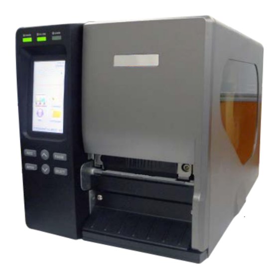
1. Introduction 1.1 Product Introduction Thank you very much for purchasing an Altec label printer. This printer is designed with die-casting aluminum chassis and print mechanism, metal cover with large clear media view window, which ensuring to work for the extreme and heavy duty industrial environment and applications. -
Page 9: Product Features
1.2 Product Features 1.2.1 Printer Standard Features The printer offers the following standard features. 203 dpi 300 dpi 600 dpi Product standard feature models models models ○ ○ ○ Thermal transfer/ or direct thermal ○ ○ ○ High quality die-cast aluminum design ○... - Page 10 Bar code, graphics/image printing Supported bar code Supported image 1D bar code 2D bar code BITMAP, BMP, PCX Code128 subsets CODABLOCK F (Max. 256 A.B.C, Code128UCC, mode, colors EAN128, Interleave 2 DataMatrix, graphics) of 5, Code 39, Code Maxicode, PDF- 93, EAN-13, EAN-8, 417, Aztec, Codabar, POSTNET,...
-
Page 11: Printer Optional Features
ISO-8859-15: Latin-9 UTF-8 1.2.2 Printer Optional Features The printer offers the following optional features. User Dealer Factory Product option feature option option option ○ Applicator I/O interface (GPIO) Main board with extended memory ( 512 MB Flash/ 256 MB ○... -
Page 12: General Specifications
1.3 General Specifications General Specifications Physical 270 mm (W) x 308 mm (H) x 515 mm (D) dimensions Weight 15 kg (33.07 Ibs) Internal switching power supply Input: AC 100-240V, 2A, 50-60Hz Power Output: DC 24V, 5A, 120W Operation: 5 ~ 40˚C (41 ~ 104˚F), 25~85% non-condensing Environmental Storage: -40 ~ 60 ˚C (-40 ~ 140˚F), 10~90% non-condensing condition... -
Page 13: Media Specifications
1.6 Media Specifications Media Specifications 203 dpi models 300 dpi models 600 dpi models Label roll capacity 208.3 mm (8.2”) OD Media alignment Edge alignment Continuous, die-cut, Fan-fold, tag, notched, black mark, Media type perforated, care label (width less than 3 inch) Media wound type Printing face outside wound Media width... -
Page 14: Operations Overview
2. Operations Overview 2.1 Unpacking and Inspection This printer has been specially packaged to withstand damage during shipping. Please carefully inspect the packaging and printer upon receiving the bar code printer. Please retain the packaging materials in case you need to reship the printer. Unpacking the printer, the following items are included in the carton. -
Page 15: Printer Overview
2.2 Printer Overview 2.2.1 Front View For MU series LED indicators LCD display Operation buttons Media view window Paper exit chute Printer cover - 8 -... - Page 16 For MT series LED indicators Touch screen Operation buttons Media view window Paper exit chute Printer cover - 9 -...
-
Page 17: Interior View
2.2.2 Interior view Ribbon rewind spindle Ribbon release button Print head pressure adjustment knobs Z axis mechanism adjustment knob Ribbon tension adjustment knob Print head release lever Media sensor lock lever Ribbon supply spindle Media guide bar & Rear label guide Label roll guard 3”... -
Page 18: Rear View
2.2.3 Rear View External label entrance chute Power cord socket Power switch Ethernet interface * SD card socket USB interface USB host RS-232C interface GPIO interface (Option) Centronics interface Note: The interface picture here is for reference only. Please refer to the product specification for the interfaces availability. - Page 19 V2.0 Class 4 Transcend V2.0 Class 4 Transcend V3.0 Class 10 UHS-I 16G Transcend Micro SD V3.0 Class 10 UHS-I 32G Transcend V3.0 Class 10 Kingston V2.0 Class 4 Scandisk V3.0 Class 10 UHS-I 16G Scandisk - The DOS FAT file system is supported for the SD card. - Folders/files stored in the SD card should be in the 8.3 filename format.
-
Page 20: Operator Control
2.3 Operator Control For MU series LEDs display Printer firmware version Printer model Keys - 13 -... - Page 21 For MT series LEDs Touch screen Icons Printer firmware version Printer model Keys - 14 -...
-
Page 22: Led Indication And Keys
2.3.1 LED Indication and Keys Status Indication Printer power off POWER Printer power on Printer is ready ON-LINE Printer is paused Blinking Printer is downloading data Printer is ready Carriage open or cutter error ERROR Blinking No paper, paper jam or no ribbon Keys Function Pause/Resume the printing process... -
Page 23: Touch Screen (Mt Series)
2.3.2 Touch Screen (MT series) Tap an item to open/use it. Be selected (Red) Return Up page Next page Scroll up Scroll down - 16 -... - Page 24 - 17 -...
-
Page 25: Setup
3. Setup 3.1 Setting up the printer 1. Place the printer on a flat, secure surface. 2. Make sure the power switch is off. 3. Connect the printer to the computer with the provided USB cable. 4. Plug the power cord into the AC power cord socket at the rear of the printer, and then plug the power cord into a properly grounded power outlet. -
Page 26: Loading The Ribbon
3.2 Loading the Ribbon 3.2.1 Loading the Ribbon Open the printer right side cover. Push the print head release lever to open the print head mechanism. Install the ribbon onto ribbon supply spindle. - 19 -... - Page 27 Thread the ribbon through the ribbon sensor slot and then through the open space in between print head and platen. Ribbon sensor Wrap the ribbon onto the ribbon rewind spindle. Wind the ribbon clockwise about 3~5 circles onto the ribbon rewind spindle until it is smooth and properly stretched.
- Page 28 Loading path for ribbon - 21 -...
-
Page 29: Remove Used Ribbon
3.2.2 Remove Used Ribbon 1. Break the ribbon between ribbon guide plate and the ribbon rewind spindle. 2. Push the ribbon release button to release the ribbon on the ribbon rewind spindle. PUSH 3. Slide off the ribbon from ribbon rewind spindle. -
Page 30: Loading The Media
3.3 Loading the Media 3.3.1 Loading the Media 1. Open the printer right side cover. 2. Push the print head release lever to open the print head mechanism. 3. Move the label roll guard horizontally to the end of label spindle then flip down the label roll guard. - Page 31 4. Place the roll of media on the label supply spindle. Flip up the label roll guard. Move the label roll guard horizontally to gently fit the width of label roll. 3” core label spindle 1” core label spindle Replace 3” core label spindle module to fit the 1” core label by removing two screws. 5.
- Page 32 6. Unlock the media sensor lock lever to adjust the media sensor, make sure the gap or black mark sensor is at the location where media gap/black mark will pass through for sensing. Unlock Lock Note: * The sensor location is marked by a triangle mark ▽ at the sensor housing. * The media sensor position is moveable, please make sure the gap or black mark is at the location where media gap/black mark will pass through for sensing.
- Page 33 Loading path for media - 26 -...
-
Page 34: Loading The Fan-Fold/External Media
3.3.2 Loading the Fan-fold/External Media Open the printer right side cover. Insert the fan-fold media through the bottom or rear external label entrance chute. Please refer to section 3.3.1 to loading media. Note: Please calibrate the gap/black mark sensor when changing media. Loading path for fan-fold labels - 27 -... -
Page 35: Loading Media In Peel-Off Mode (Option)
3.3.3 Loading Media in Peel-off Mode (Option) 1. Open the printer right side cover. 2. Please refer to section 3.3.1 step 3~9 for loading media. 3. Using the front display panel to do the calibration first and set the printer mode to peeler mode. - Page 36 7. Wrap the label onto the internal rewind spindle and wind the spindle counter-clockwise about 3~5 circles until the label is properly stretched. 8. Lift up the peel-off roller release lever and close the print head mechanism. PUSH PUSH 9. Peeling will automatically start. Press the FEED button to test.
-
Page 37: Remove Liner From Internal Rewind (Option)
3.3.4 Remove Liner from Internal Rewind (Option) 1. Break the liner between peel-off roller and the internal rewind spindle. 2. Push the liner release button to release the liner on the internal rewind spindle. 3. Slide off the liner from internal rewind spindle. -
Page 38: Loading Media In Rewind Liner With Label Mode (Option)
3.3.5 Loading Media in Rewind Liner with Label Mode (Option) This mode can rewind the media including liner and label on the rewind spindle 1. Open the printer right side cover and the print head mechanism. 2. Insert the supply holder guide and paper core into the internal rewind for 1” core label roll. Insert the supply holder guide, 3”... -
Page 39: Remove Labels From Internal Rewind (Option)
3.3.6 Remove Labels from Internal Rewind (Option) 1. Slide off the labels with supply holder guides from internal rewind spindle. Supply holder guides - 32 -... -
Page 40: Adjustment Knob
4. Adjustment Knob 4.1 Print Head Pressure Adjustment knob The print head pressure adjustment knob has 5 levels of adjustment. Because the printer’s paper alignment is to the left side of mechanism, different media widths require different pressure to print correctly. -
Page 41: Ribbon Tension Adjustment Module
4.2 Ribbon Tension Adjustment Module Adjustment knob The ribbon tension adjustment knob has 0 ~ 5 positions for adjustment. Because the printer’s ribbon alignment is to the left side of mechanism, different ribbon or media widths require different tension to print correctly. Therefore it may require to adjust the ribbon tension knob to get your best print quality. -
Page 42: Print Head Burn Line Adjustment Knob
4.3 Print Head Burn Line Adjustment Knob The print head burn line adjustment knobs are used to fine tune the print quality for different thickness of media. Turning the knobs adjusts the print head’s burn line forward or backward as it relates to the platen roller. -
Page 43: Mechanism Fine Adjustment To Avoid Ribbon Wrinkles
4.4 Mechanism Fine Adjustment to Avoid Ribbon Wrinkles This printer has been fully tested before delivery. There should be no ribbon wrinkle presented on the media for general-purpose printing application. Ribbon wrinkle is related to the media thickness, print head pressure balance, ribbon film characteristics, print darkness setting…etc. In case the ribbon wrinkle happens, please follow the instructions below to adjust the printer parts. - Page 44 If the wrinkle on the label starts from the If the wrinkle on the label starts from the lower left side to upper right side, please do lower right side to upper left side, please do following adjustment. following adjustment. 1.
-
Page 45: Lcd Menu Function For Mt Series
5. LCD Menu Function for MT Series 5.1 Enter the Main Menu * By Keys: Press the “MENU” button and press the “SELECT” button to enter the main menu. * By touch display: Tap the “Menu” icon on LCD to enter the main menu. - 38 -... -
Page 46: Main Menu Overview
5.2 Main Menu Overview There are 8 categories for the main menu. You can easy to set the settings of printer without connecting the computer. Please refer to following sections for more details. Menu File TSPL ZPL2 Sensor Interface Advance Service Diagnostics Manager... -
Page 47: Tspl2
5.3 TSPL2 This “TSPL2” category can set up the printer settings for TSPL2. Speed Density None Direction Batch Mode Print mode Peeler Mode Offset Cutter Mode Menu TSPL Shift X Cutter Batch Shift Y Reference X Reference Y Code Page Country Item Description... - Page 48 Batch Mode Once image is printed completely, label gap/black mark will be fed to the tear plate location for tear away. Peeler Mode Enable the label peel off mode. Cutter Mode Enable the label cutter mode. Cutter Batch Cut the label once at the end of the printing job. This item is used to fine tune media stop location.
-
Page 49: Zpl2
ZPL2 This “ZPL2” category can set up the printer settings for ZPL2. Darkness Print Speed Tear Off Tear Off Print Mode Peeler Off Print Width Cutter List Fonts List Images List Formats List Setup Control Prefix Format Prodix Feed Delimiter Char Menu ZPL2 Calibration... - Page 50 Use this item to setup print speed. Available setting 203 dpi: 6 Print Speed 300 dpi: 4 range is 4~12 for 203dpi, 2~12 for 300dpi and 1.5 ~6 for 600dpi. 600 dpi: 3 This item is used to fine tune media stop location. Tear Off +000 Available setting value is from “+”...
- Page 51 When reprint mode is enabled, you can reprint the last Reprint Mode Disabled label printer by pressing button on printer’s control panel. Selects the bitmap scaling factor. The first number is the Format Convert original dots per inch (dpi) value; the second, the dpi to None which you would like to scale.
-
Page 52: Sensor
Sensor This option is used to calibrate the selected sensor. We recommend calibrate the sensor before printing when changing the media. Auto Calibration Black Mark Continuous Manual Setup Black Mark Menu Sensor Continuous Auto Threshold Detect Fixed Maximum Length Advanced Item Description Default... -
Page 53: Interface
Interface This option is used to set the printer interface settings. Serial Menu Interface Ethernet 5.6.1 Serial Comm. This option is used to set the printer RS-232 settings. 1200 bps 2400 bps 4800 bps 9600 bps Baud Rate 19200 bps 38400 bps 57600 bps 115200 bps... -
Page 54: Ethernet
5.6.2 Ethernet Use this menu to configure internal Ethernet configuration check the printer’s Ethernet module status, and reset the Ethernet module. Status Menu Interface Ethernet DHCP Configure Static IP Item Description Default Use this menu to check the Ethernet IP address and Status MAC setting status. -
Page 55: File Manager
5.7 File Manager This feature is used to check the printer available memory and file list. DRAM Menu File Manager FLASH Item Description Use this menu to show, delete and run (.BAS) the files saved in DRAM the printer DRAM memory. Use this menu to show, delete and run (.BAS) the files saved in FLASH the printer Flash memory. -
Page 56: Diagnostics
5.8 Diagnostics Print Config. Dump Mode Print Head Menu Diagnostics Display Sensor 5.8.1 Print Config. This feature is used to print current printer configuration to the label. On the configuration printout, there is a print head test pattern, which is useful for checking if there is any dot damage on the print head heater element. - Page 57 ZPL setting information Print darkness Print speed (inch/sec) Label size Control prefix Format prefix Delimiter prefix Printer power up motion Printer head close motion Note: ® ZPL is emulating for Zebra language. RS232 serial port configuration Numbers of download files Total &...
-
Page 58: Dump Mode
5.8.2 Dump Mode Captures the data from the communications port and prints out the data received by printer. In the dump mode, all characters will be printed in 2 columns. The left side characters are received from your system and right side data are the corresponding hexadecimal value of the characters. -
Page 59: Print Head
5.8.3 Print Head This feature can check the temperature, resistance and bad dots for print head. Menu Diagnostics Print Head 5.8.4 Display This feature can check the display for printer. Menu Diagnostics Display 5.8.5 Sensor This feature can check the intension & reading values for printer sensors. Menu Diagnostics Sensor... -
Page 60: Advanced
5.9 Advanced This feature is used to set the printer advanced settings. Display Brightness Touchscreen Calibration Menu Advanced Date & Time Cutter Type Language Item Description Display This item is used to setup the brightness for display. Brightness Touchscreen This item is used to calibrate the center of the cross for best result Calibration for touchscreen. -
Page 61: Service
5.10 Service This feature is used to restore printer settings to defaults and checking information for printer. Initialization Menu Service Printer Information Contact us Item Description Initialization This feature is used to restore printer settings to defaults. Printer This feature is used to check printer serial number, printed mileage(m), Information labels(pcs.) and cutting counter. -
Page 62: Lcd Menu Function For Mu Series
6. LCD Menu Function for MU Series 6.1 Enter the Main Menu Press button to enter the main menu or to cancel the setting and return to the previous menu. Press button to scroll up the menu list. Press button to scroll down the menu list. -
Page 63: Setup
6.3 Setup This “Setup” category can set up the printer settings for TSPL2, ZPL2, sensor, serial interface, and Ethernet interface. 6.3.1 Printer Setup (TSPL2/ ZPL2) TSPL2 This “TSPL” category can set up the printer settings for TSPL2. Speed Density None Direction Batch Mode Print mode... - Page 64 The direction setting value is either 1 or 0. Use this item to setup the printout direction. DIRECTION 0 DIRECTION 1 Direction This item is used to set the print mode. There are 5 modes as below, Printer Mode Description Next label top of form is aligned to the print head None Batch...
- Page 65 ZPL2 This “ZPL2” category can set up the printer settings for ZPL2. Darkness Print Speed Tear Off Tear Off Print Mode Peeler Off Print Width Cutter List Fonts List Images List Formats List Setup Control Prefix Format Prodix Feed Main Printer Delimiter Char Setup...
- Page 66 This item is used to fine tune media stop location. Tear Off +000 Available setting value is from “+” to “-” or “0” to “9”. This item is used to set the print mode. There are 3 modes as below, Printer Mode Description Print mode...
- Page 67 original dots per inch (dpi) value; the second, the dpi to which you would like to scale. Note: If printing from enclosed software/driver, the software/driver will send out the commands, which will overwrite the settings set from the panel. - 60 -...
-
Page 68: Sensor
6.3.2 Sensor This option is used to calibrate the selected sensor. We recommend calibrate the sensor before printing when changing the media. Automatic Gap Mode Manual Pre-Printed Status Automatic Main Setup Sensor Menu Calibration Bline Mode Manual Pre-Printed Automatic Cont. Mode Manual Item Description... -
Page 69: Serial Comm
6.3.3 Serial Comm. This option is used to set the printer RS-232 settings. 1200 bps 2400 bps 4800 bps 9600 bps Baud Rate 19200 bps 38400 bps 57600 bps 115200 bps None Main Menu Setup Serial Comm. Parity Even Data Bits Stop Bit(s) Item Description... -
Page 70: File Manager
6.4 File Manager This feature is used to check the printer available memory and file list. DRAM Flie List FLASH Avail. Memory CARD Main Menu File Manager DRAM Del. All Files FLASH CARD Item Description Use this menu to show, delete and run (.BAS) the files saved in File List the printer DRAM/Flash/Card memory. -
Page 71: Diagnostics
6.5 Diagnostics Print Config. Menu Diagnostics Dump Mode Rotate Cutter 6.5.1 Print Config. This feature is used to print current printer configuration to the label. On the configuration printout, there is a print head test pattern, which is useful for checking if there is any dot damage on the print head heater element. - Page 72 ZPL setting information Print darkness Print speed (inch/sec) Label size Control prefix Format prefix Delimiter prefix Printer power up motion Printer head close motion Note: ® ZPL is emulating for Zebra language. RS232 serial port configuration Numbers of download files Total &...
-
Page 73: Dump Mode
6.5.2 Dump Mode Captures the data from the communications port and prints out the data received by printer. In the dump mode, all characters will be printed in 2 columns. The left side characters are received from your system and right side data are the corresponding hexadecimal value of the characters. -
Page 74: Rotate Cutter
6.5.3 Rotate Cutter In case paper is jammed in the cutter, this feature can rotate the cutter blade forward or reverse direction, which is helpful to remove the jammed paper easily from the cutter. Main Menu Diagnostics Rotate Cutter - 67 -... -
Page 75: Language
6.6 Language display This item is used to setup the language on English Chinese (TC) Chinese (SC) Japanese Korean German Italian Main Menu Language French Russian Polosh Spanish Lithuanian Czech Portuguese Serbian - 68 -... -
Page 76: Service
6.7 Service This feature is used to restore printer settings to defaults and checking information for printer. Initialization Mileage Info. Menu Service Serial Info. Maintenance Info Item Description Initialization This feature is used to restore printer settings to defaults. Mileage Info. This feature is used to check the printed mileage Serial Info. -
Page 77: Diagnostic Tool
7. Diagnostic Tool TSC’s Diagnostic Utility is an integrated tool incorporating features that enable you to explore a printer’s settings/status; change a printer’s settings; download graphics, fonts and firmware; create a printer bitmap font; and send additional commands to a printer. With the aid of this powerful tool, you can review printer status and setting in an instant, which makes it much easier to troubleshoot problems and other issues. -
Page 78: Printer Function
7.2 Printer Function 1. Connect the printer and computer with a cable. 2. Select the PC interface connected with bar code printer. USB cable Other cable The default interface setting is USB interface. If USB interface is connected with printer, no other settings need to be changed in the interface field. -
Page 79: Setting Ethernet By Diagnostic Tool
7.3 Setting Ethernet by Diagnostic Tool The Diagnostic Utility is enclosed in the CD disk \Utilities directory. Users can use Diagnostic Tool to setup the Ethernet by RS-232, USB and Ethernet interfaces. The following contents will instruct users how to configure the Ethernet by these three interfaces. 7.3.1 Using USB interface to setup Ethernet interface 1. -
Page 80: Using Rs-232 Interface To Setup Ethernet Interface
7.3.2 Using RS-232 interface to setup Ethernet interface 1. Connect the computer and the printer with a RS-232 cable. 2. Turn on the printer power. 3. Start the Diagnostic Utility by double clicks on the icon. 4. Select “COM” as interface then click on the “Setup” button to setup the serial port baud rate, parity check, data bits, stop bit and flow control parameters. -
Page 81: Using Ethernet Interface To Setup Ethernet Interface
6.3.3 Using Ethernet interface to setup Ethernet interface 1. Connect the computer and the printer to the LAN. 2. Turn on the printer power. 3. Start the Diagnostic Utility by double clicks on the icon. 4. Select “Ethernet” as the interface then click on the “Setup” button to setup the IP address, subnet mask and gateway for the on board Ethernet. - Page 82 6. Select the printer in the left side of listed printers, the correspondent IP address will be shown in the right side “IP address/Printer Name” field. 7. Click “Change IP Address” to configure the IP address obtained by DHCP or static. The default IP address is obtained by DHCP.
-
Page 83: Troubleshooting
8. Troubleshooting The following guide lists the most common problems that may be encountered when operating this bar code printer. If the printer still does not function after all suggested solutions have been invoked, please contact the Customer Service Department of your purchased reseller or distributor for assistance. - Page 84 * SD card is damaged. * Use the supported capacity SD card. * SD card doesn’t insert * Insert the SD card again. SD card is unable to use correctly. * The supported SD card spec and the * Use the non-approved SD approved SD card manufacturers, card manufacturer.
- Page 85 * Calibrate the sensor sensitivity again. * Set the correct label size and gap size. * Press [MENU] [SELECT] x3[DOWN]x6 [SELECT] to fine tune the parameter of Shift Y. * If using the software BarTender, please set the vertical offset in the driver. * Media sensor sensitivity is not set properly.
-
Page 86: Maintenance
9. Maintenance This session presents the clean tools and methods to maintain your printer. 1. Please use one of following material to clean the printer. Cotton swab Lint-free cloth Vacuum / Blower brush 100% Ethanol or Isopropyl Alcohol 2. -
Page 87: Revise History
Revise History Date Content Editor 2015/6/26 Modify section 1.6 Camille 2015/7/31 Modify section 3.3.3 (Loading media in peel-off mode) Camille 2015/10/19 Modify section 2.2.3 (Recommended SD card specification) Camille Add section 4.2 (Ribbon Tension Adjustment Module) 2015/11/9 Modify section 4.4 (Mechanism Fine Adjustment to Avoid Ribbon Camille Wrinkles) 2016/5/27... - Page 89 Nederland België Nieuwland Parc 159 Erasmuslaan 11 3351 LJ Papendrecht 1804 Eppegem Tel: +31(0)78 615 20 33 Tel: +32(0)2 270 34 88 E-mail: info@altec.nl E-mail: info@altec.be Website: www.altec.nl Website: www.altec.be...
Need help?
Do you have a question about the ATP-4310 and is the answer not in the manual?
Questions and answers