Table of Contents
Advertisement
Quick Links
Advertisement
Table of Contents

Related Manuals for Side-Power SLEIPNER RCT-20U


Summary of Contents for Side-Power SLEIPNER RCT-20U
- Page 1 User Manual REMOTE TRANSMITTER RCT-20U & RCT-21U & RCT-22U & RCT-23U RECEIVER RCR-2U & RCRS-2U To download your language go to www.side-power.com SLEIPNER AS P.O. Box 519 N-1612 Fredrikstad Norway Document id: 5488 www.side-power.com Revision: Date: 2021 © Sleipner Motor AS 2021...
-
Page 2: Table Of Contents
Contents Considerations and Precautions ........... 3 Products Signals Considerations and Precautions......3 Safety Information ..............3 SM904972 | RC-20U - RADIO CONTROL KIT SM904973 | RC-21U - RADIO CONTROL KIT Installation Manual SM904974 | RC-22U - RADIO CONTROL KIT Remote Control Kits ..............4 SM904975 | RC-23U - RADIO CONTROL KIT Panel Layout &... -
Page 3: Considerations And Precautions
S-link control system without the designated and approved interface will render all warranties and responsibilities for the complete line of Side-Power products connected void and null. If you are interfacing by agreement with Sleipner and through a designated Side-Power supplied interface, you are still required to also install at least one original Side-Power control panel to enable effi... -
Page 4: Remote Control Kits
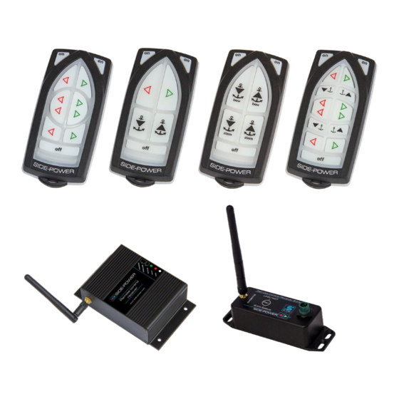
Remote Control Kits MC_0228 Remote control kit RC-20U/E consists of: Remote control kit RC-21U/E consists of: Receiver: Part no. RCR-2U/E Receiver: Part no. RCR-2U/E Transmitter (incl. Battery): Part no. RCT-20U/E Transmitter (incl. Battery): Part no. RCT-21U/E Holding bracket for transmitter unit: Part no. RC-HOLDER Holding bracket for transmitter unit: Part no. -
Page 5: Panel Layout & Functions
Remote Layout & Functions MC_0175 Remote Transmitter RCT-20(U/E) RCT-21(U/E) *U For the USA confi guration *U For the USA confi guration *E For European confi guration *E For European confi guration Turn ‘ON’ the Turn ‘ON’ the remote radio remote radio Bow directional control for Dual Bow and stern Directional control... -
Page 6: Technical Specifications
Ø 4.5 Ø 3 Ø 3 MG_0191 Transmitter/Receiver - Technical Specifi cations MC_0225 Transmitter Receiver Power feed 1x3V battery (type: CR2032) 12V or 24V power source Frequency (MHz) 914-917 MHz 914-917 MHz RF-power <10mW <10mW Operation temp. -10°C / +55°C -10°C / +55°C HxWxD (mm) 107x47x21... -
Page 7: Receiver Installation
Mount the receiver by using the 4 holes MG_0193 Receiver Installation MC_0177 ! Please refer to the graphic for special considerations relating to your model ! • Install the receiver minimum 1 meter (3ft) from high power cables and data communication cables or other sources of electrical interference, i.e. navigation instruments, radio communication devices, electric motors and generators. -
Page 8: Technical Wiring Diagram
Technical Wiring Diagram IMPORTANT Cables/wires must be cable tied well. To Thruster To Thruster Control Panel Control Panel RCT-20(U/E) STERN To Bow To Stern Thruster Thruster BLACK FUSE Ba�ery 12/24V IMPORTANT Power cables must be connected to the battery as shown. Remaining wires must be cable tied well. - Page 9 Technical Wiring Diagram IMPORTANT Cables/wires must be cable tied well. To Thruster To Thruster Control Panel Control Panel RCT-21(U/E) STERN To Bow To Stern Thruster Thruster BLACK FUSE Ba�ery 12/24V IMPORTANT Power cables must be connected to the battery as shown. Remaining wires must be cable tied well.
- Page 10 Technical Wiring Diagram IMPORTANT Cables/wires must be cable tied well. To Thruster To Thruster Control Panel Control Panel RCT-22(U/E) STERN To Bow To Stern Thruster Thruster BLACK FUSE Ba�ery 12/24V IMPORTANT Power cables must be connected to the battery as shown. Remaining wires must be cable tied well.
- Page 11 Technical Wiring Diagram IMPORTANT Cables/wires must be cable tied well. To Thruster To Thruster Control Panel Control Panel RCT-23(U/E) STERN To Bow To Stern Thruster Thruster BLACK FUSE Ba�ery 12/24V IMPORTANT Power cables must be connected to the battery as shown. Remaining wires must be cable tied well.
-
Page 12: Output Signals Diagram
Output Signals Diagram RED - Thruster Positive Thruster Bow BLUE - Thruster STBD GREY - Thruster PORT YELLOW - Automatic Main switch Enable RED - Thruster Positive BLUE - Thruster STBD Thruster Stern GREY - Thruster PORT YELLOW - Automatic Main switch Enable RED - Common BLUE - Windlass IN Windlass Bow... -
Page 13: Programming Additional Transmitters/ Remote Controls
Pair Button Pair Button Pair Button Pair Button MG_0197 Programming Additional Transmitters/ Remote Controls MC_0181 ! Please refer to the graphic for special considerations relating to your model ! The original transmitter and receiver have the same factory pre-set code so that no programming is necessary. When additional transmitters remote controls are to be used, the additional transmitters/remote controls have to be paired with the receiver. -
Page 14: S-Link Receiver Installation
Mount the receiver by using the 4 holes MG_0193 S-Link Receiver Installation MC_0183 ! Please refer to the graphic for special considerations relating to your model ! • Install the receiver minimum 1 meter (3ft) from high power cables and data communication cables or other sources of electrical interference, i.e. navigation instruments, radio communication devices, electric motors and generators. -
Page 15: Technical Wiring Diagram
Technical Wiring Diagram MG_0195 RCT 20U, 21U, 22U, 23U & REMOTE RECEIVER 5488 2021... -
Page 16: S-Link Receiver Installation
Pair Button Pair Button Pair Button Pair Button MG_0200 Programming Additional Transmitters/ Remote Controls MC_0202 ! Please refer to the graphic for special considerations relating to your model ! The original transmitter and receiver have the same factory pre-set code so that no programming is necessary. When additional transmitters remote controls are to be used, the additional transmitters/remote controls have to be paired with the receiver. -
Page 17: Transmitter Installation And Battery Replacement
Battery MG_0194 Transmitter Installation and Battery Replacement MC_0178 ! Please refer to the graphic for special considerations relating to your model ! Open the transmitter case by removing the 3 torx screws. Remove the battery by inserting a screwdriver or similar between battery and holder at point A and fl ip the battery out, taking care not to damage the battery grips at point B. -
Page 18: Important Thruster User Considerations And Precautions
Important Thruster User Considerations and Precautions MC_0179 IMPORTANT Failure to follow the Considerations and precautions can cause serious injury / damage and will render all warranty given by Sleipner Motor AS VOID. • Ensure you know the location of the main battery switch that disconnects the thruster from all power sources (batteries) so the thruster can be turned off... -
Page 19: Thruster Operation
Turn on the main power switch for the bow thruster. (NB: Always turn off the main power switch when not on-board.) Turn on the control panel by pushing both “ON” buttons on the original Side-Power panel simultaneously. (NB: If another type of control is installed, push the On/Off... - Page 20 Activating the bow thruster Activating the stern thruster Activating both bow and Activating both bow and stern thruster to push the stern thruster to rotate the boat sideways boat on axis Activating lowers Anchor/ Activating raises Anchor/ Windlass Windlass MG_0190 RCT 20U, 21U, 22U, 23U &...
-
Page 21: Transmitter Led Operation And Alarm Indication
Transmitter LED Operation and Alarm Indication MC_0182 State LED status Alarm status Transmitter ON The yellow LED’s No sound blink each second Buttons activated The yellow LED’s No sound blink fast Pairing mode All LED’s on No sound Connection lost Red LED is blink- 3 beeps from the ing once each... - Page 22 Notes MC_0037 ..............................................................................................................................................................................................................................................................................................................................................................................................................................................................................................................................................................................................................................................................................................................................................................................................................................................................................................................................................................................................................................................................................................................................................................................................................................................................................................................................................................................................................................................................................................................................................................................................................RCT 20U, 21U, 22U, 23U & REMOTE RECEIVER 5488 2021...
- Page 23 Notes MC_0037 ..............................................................................................................................................................................................................................................................................................................................................................................................................................................................................................................................................................................................................................................................................................................................................................................................................................................................................................................................................................................................................................................................................................................................................................................................................................................................................................................................................................................................................................................................................................................................................................................................................RCT 20U, 21U, 22U, 23U & REMOTE RECEIVER 5488 2021...
- Page 24 www.sleipnergroup.com SLEIPNER AS * AS P.O. Box 519 * N-1612 Fredrikstad * Norway The information given in the document was correct at the time it was published. However, Sleipner Motor AS can not accept liability for any inaccuracies or omissions it may contain.
Need help?
Do you have a question about the SLEIPNER RCT-20U and is the answer not in the manual?
Questions and answers